
Air-inflation meridian tire for heavy load

A technology for radial tires and heavy loads, applied to the field of pneumatic radial tires for heavy loads, to achieve the effect of improving durability and suppressing shear deformation

Inactive Publication Date: 2005-07-20
BRIDGESTONE CORP
View PDF1 Cites 3 Cited by
  • Summary
  • Abstract
  • Description
  • Claims
  • Application Information

AI Technical Summary

Problems solved by technology

However, there is no technology that can well solve these contradictory problems

Method used


Image

  • Air-inflation meridian tire for heavy load
  • Air-inflation meridian tire for heavy load

Examples


Embodiment Construction

[0019] Hereinafter, embodiments of the present invention will be described based on the drawings.

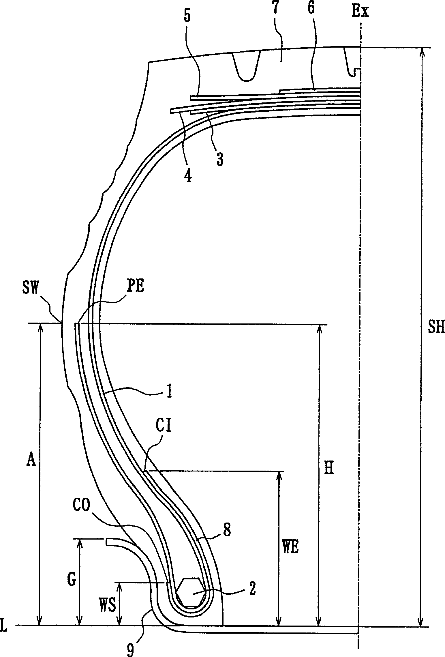
[0020] figure 1 It is a cross-sectional view showing the tread portion of the left half of the tire in the width direction when the tire according to one embodiment of the present invention is mounted on an applicable rim and filled with a predetermined air pressure. The right half is symmetrical to the left half with the central line Ex as the axis.

[0021] In the figure, 1 denotes a carcass layer, which is developed in a ring shape between bead cores 2, and its side parts are wound around each bead core 2 from the inner side to the outer side of the tire. On the outer peripheral side of the top of the carcass layer 1 , four belt layers 3 , 4 , 5 , 6 are arranged, and a tread rubber 7 is arranged on the outer peripheral side of the belt layer 6 . Further, a wire chafer 8 as a carcass reinforcement is wound around the bead core 2 along the outer side of the carcass layer 1 wo...


PUM


Abstract

The invention provides a pneumatic radial tire for a heavy load capable of optimizing a providing position of a rewinding end of a carcass ply or a wire chafer end, preventing a crack from beginning at the end part, and improving durability in the part and in the whole tire by suppressing collapse of a side wall part and a bead part.

Description

technical field [0001] The present invention relates to a pneumatic radial tire for heavy loads suitable for use on trucks, buses, construction vehicles, etc., characterized by preventing the development of turtles from the ends of carcass ply and wire chafer Pneumatic radial tires for heavy loads that prevent cracking and prevent deflection of the sidewall and bead when the load rotates, thereby improving durability. Background technique [0002] In radial tires for heavy loads, as described in JP-A-2000-185516, steel wire bead packs are generally placed on the wound portion of the carcass layer without direct contact between the carcass layer and the rim. outside to protect the carcass. Especially when such tires are used as spare tires many times after the tread wears out, the parts where the stress tends to concentrate during driving on the road, such as the winding end of the carcass layer and the wire bead bag Cracks tend to occur at the ends of the cloth and the lik...

Claims


Application Information

Patent Timeline
IPC IPC(8): B60C15/06B60C15/00
Inventor 富永达雄
Owner BRIDGESTONE CORP
Learn More