Simple ratchet spanners

A ratchet wrench, a simple technology, applied to wrenches, manufacturing tools, wrenches, etc., can solve the problems of complex structure, high manufacturing cost, hindering the popularization and promotion of fast ratchet wrench, etc., and achieve the effect of simple structure improvement and obvious effect

Inactive Publication Date: 2005-07-27
刘松土
View PDF2 Cites 0 Cited by
  • Summary
  • Abstract
  • Description
  • Claims
  • Application Information

AI Technical Summary

Problems solved by technology

However, due to the defects of complex structure and high manufacturing cost in the existing ratchet wrench, the popularization of fast ratchet wrench is hindered.

Method used


Image

  • Simple ratchet spanners
  • Simple ratchet spanners

Examples


Embodiment Construction

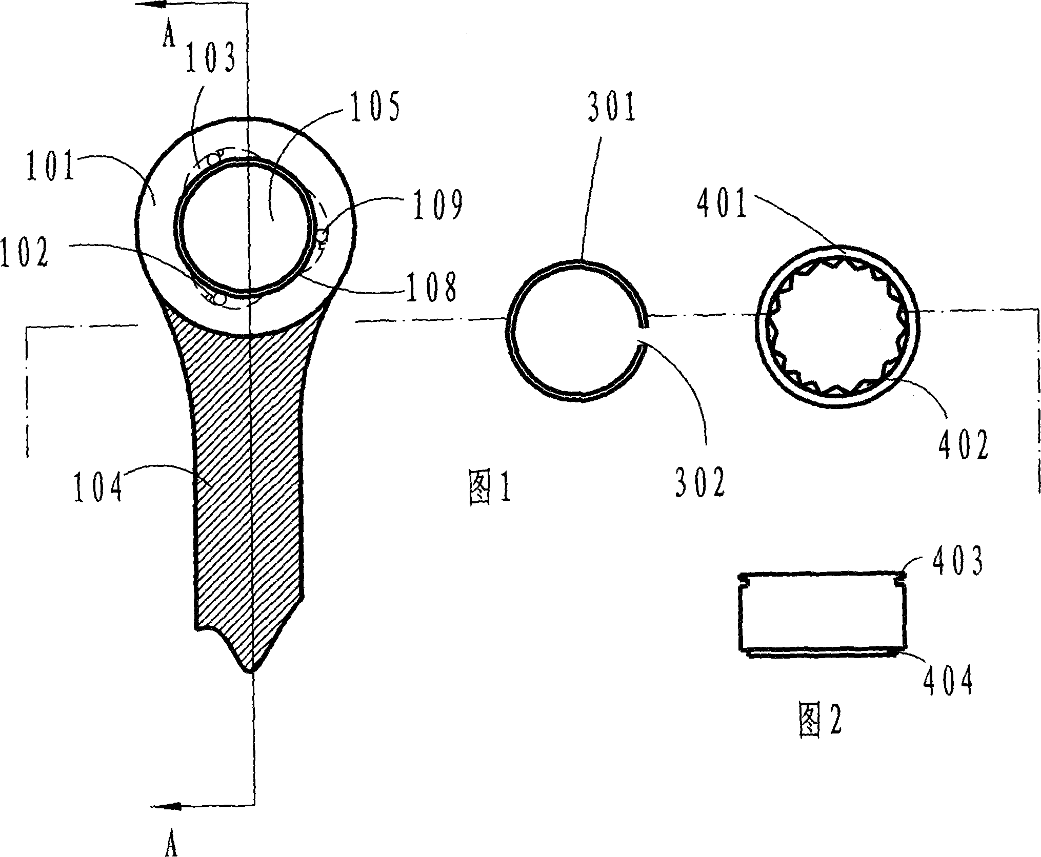
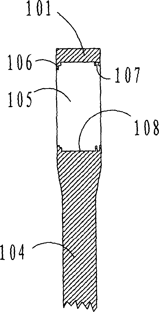
[0012] The serial numbers in the figure indicate respectively: head 101, needle roller stopper 102, slope-shaped concave surface 103, handle 104; through hole 105, shrinking platform 106, circlip groove 107, inner edge wall 108; needle roller 109; Spring 301, circlip opening 302; working torsion plate 401, working teeth 402, working torsion plate circlip groove 403, annular flange 404.

[0013] The present invention will be further described in detail through the embodiments below in conjunction with the accompanying drawings.

[0014] Referring to Figures 1-3, Figure 1 shows an exploded view of the present invention. It includes a wrench body and a working twist plate 401. The wrench body consists of a head 101 and a handle 104. A through hole 105 that can receive the working twist plate 401 is formed on the head 101. The through hole 105 is circular. Several slope-shaped concave surfaces 103 are formed on the inner edge wall 108 of the through hole 105 of the head 101 . In...


PUM


Abstract

A simple ratchet wrench is composed of a main body consisting of a head with a through hole and a turning ring fixed in said through hole. It features that several sloped surfaces are made on the inner surface of said through hole and each sloped surface has a radial roller in contact with the smooth peripheral surface of said turning ring.

Description

technical field [0001] The invention belongs to a hardware tool for screwing hexagonal, square and other nuts, in particular to a fast ratchet wrench. Background technique [0002] A wrench is a common tool for tightening nuts. Before the present invention was made, various forms of wrenches had been publicly used on the market, such as combination wrenches, open-ended wrenches, ring wrenches, ratchet wrenches and the like. Because the ratchet wrench can work continuously, it is favored by consumers and develops rapidly. However, due to the defects of complex structure and high manufacturing cost in the existing ratchet wrench, popularization of the fast ratchet wrench is hindered. A common feature of this type of ratchet wrench is that the inner wall of the head is provided with a rack, such as the ratchet wrench involved in US Pat. No. 4,520,697 and No. 3,337,014. It utilizes the gear rack on the inner edge wall to cooperate with the bow-shaped teeth or the teeth on the...

Claims


Application Information

Patent Timeline
Patent Type & Authority Applications(China)
IPC IPC(8): B25B13/46
Inventor 刘松土
Owner 刘松土
Why Eureka
Try Eureka