Valve operating device for internal combustion engine

A transmission device, internal combustion engine technology, applied in the direction of internal combustion piston engine, valve device, combustion engine, etc., can solve the problems of reduced thermal efficiency, reduced output power, increased exhaust loss of combustion gas, etc., to prevent and suppress intake air blowback. Effect

Inactive Publication Date: 2005-07-27
HONDA MOTOR CO LTD
View PDF1 Cites 0 Cited by
  • Summary
  • Abstract
  • Description
  • Claims
  • Application Information

AI Technical Summary

Problems solved by technology

In addition, in the current technology, since the drive shaft and the control shaft are respectively provided in the respective variable valve trains on the side of the intake valve and the side of the exhaust valve, a valve for controlling the intake valve and the exhaust valve is formed. Increased size of variable mechanism for operating characteristics
Moreover, when the opening and closing timing of the intake valve or exhaust valve is formed into an advanced angle or a retarded angle, if the opening and closing timing of the exhaust valve is too late, the exhaust loss of the combustion gas will increase and the thermal efficiency will decrease; In addition, if the opening timing of the intake valve is too early, it will not be able to take in enough fresh air, the output power will drop, and the combustion will be unstable.

Method used


Image

  • Valve operating device for internal combustion engine
  • Valve operating device for internal combustion engine
  • Valve operating device for internal combustion engine

Examples


Embodiment Construction

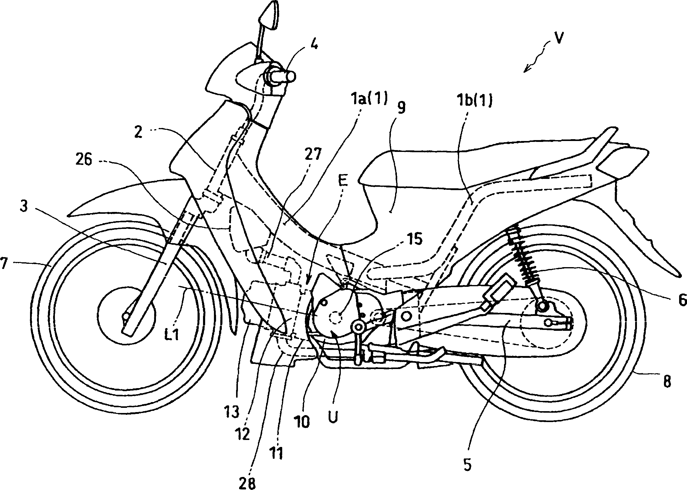
[0066] Below, refer to Figure 1 to Figure 14 Embodiments of the present invention will be described.

[0067] see figure 1 , the internal combustion engine E to which the present invention is applied is mounted on a vehicle, a two-wheeled motor vehicle V. The two-wheeled vehicle V has: a vehicle frame 1 including a front frame 1a and a rear frame 1b; a handle 4 fixed to the upper end of a front fork 3 rotatably supported on a front main pipe 2 connected to the front frame 1a ; the front wheel 7 rotatably supported on the lower end of the front fork 3 ; the power unit U supported on the vehicle frame 1 ; the rear wheel 8 rotatably supported on the rear end of the swing arm 5 , which can swing The rear shock absorber 6 connecting the rear part of the rear frame 1b and the swing arm 5; the vehicle body cover 9 surrounding the vehicle frame 1.

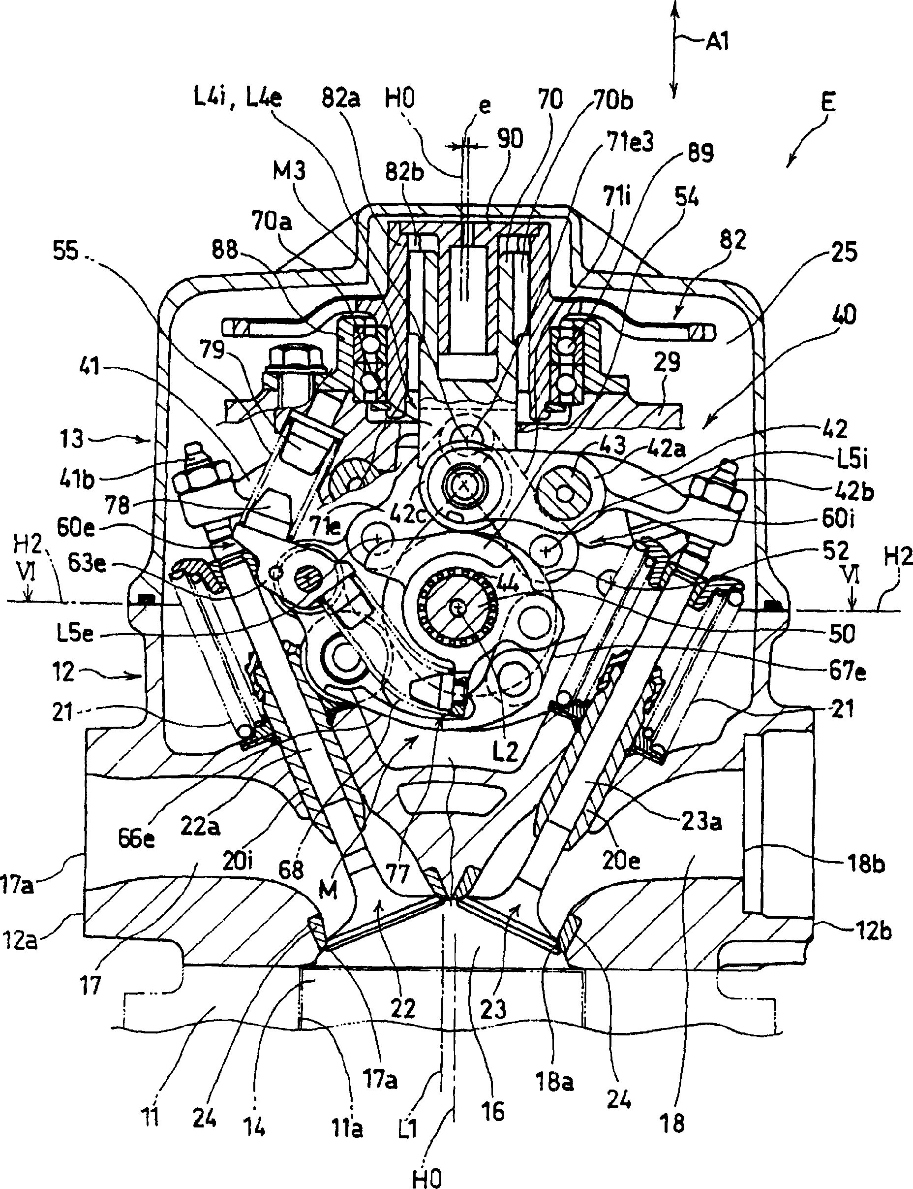
[0068] The power unit U includes: a transverse internal combustion engine E having a crankshaft 15 extending in the left-right direct...


PUM


Abstract

The object of this invention is to prevent or suppress the blow back of intake air and suppress the lowering of fuel economy due to the lowering of an effective expansion ratio by starting to open an intake valve when a pressure in a combustion chamber is low. The valve characteristic variable mechanism M of a valve system 40 controls an internal EGR rate by controlling an overlapping period and a non-overlapping period. The valve characteristic variable mechanism M comprises a control mechanism M3 swinging an intake link mechanism connected to an intake cam and an exhaust link mechanism connected to an exhaust cam 54 about a camshaft 50 and a drive mechanism driving the control mechanism M3. The control mechanism M3 connects the drive mechanism to each link mechanism so that the spark-retard angle of an intake valve 22 at an opening time by an intake link mechanism is larger than the spark-advance angle of an exhaust valve 23 at a closing timing by an exhaust link mechanism relative to the same drive amount of the drive mechanism in the increasing direction of an internal EGR rate.

Description

technical field [0001] The present invention relates to a valve transmission device of an internal combustion engine having a valve characteristic changing mechanism for controlling the valve action characteristics of an intake valve and an exhaust valve. Override time and non-override time, thereby, control the internal EGR (exhaust gas recirculation) rate of the internal combustion engine's valve train. Background technique [0002] It is well known that internal EGR is performed by leaving part of the burned gas in the combustion chamber, thereby reducing the intake loss of the internal combustion engine, improving fuel consumption performance, and reducing NOx in exhaust gas to improve exhaust gas purification performance. Furthermore, as a device for performing internal EGR and controlling valve operation characteristics of intake valves and exhaust valves, for example, a variable valve train for an internal combustion engine disclosed in Patent Document 1. The variabl...

Claims


Application Information

Patent Timeline
Patent Type & Authority Applications(China)
IPC IPC(8): F01L13/00F01L1/34F02D13/00F02D13/02
CPCF01L1/022F01L13/0021F01L2105/02F01L2105/00F01L1/181F01L2001/0476F01L13/0015F01L2820/032F01L2305/00F01L2305/02Y02T10/12
Inventor 井元丰田边和也堤崎高司
Owner HONDA MOTOR CO LTD
Why Eureka
Try Eureka