Double cylinder rotary compressor
A technology of rotary compressor and double cylinder, which is applied in the direction of rotary piston machinery, rotary piston pump, rotary piston type/oscillating piston type pump components, etc. It can solve the problems of sealing deterioration and achieve high reliability and prevent Rotational, high-reliability effects
- Summary
- Abstract
- Description
- Claims
- Application Information
AI Technical Summary
Problems solved by technology
Method used
Image

Examples
Embodiment approach 1
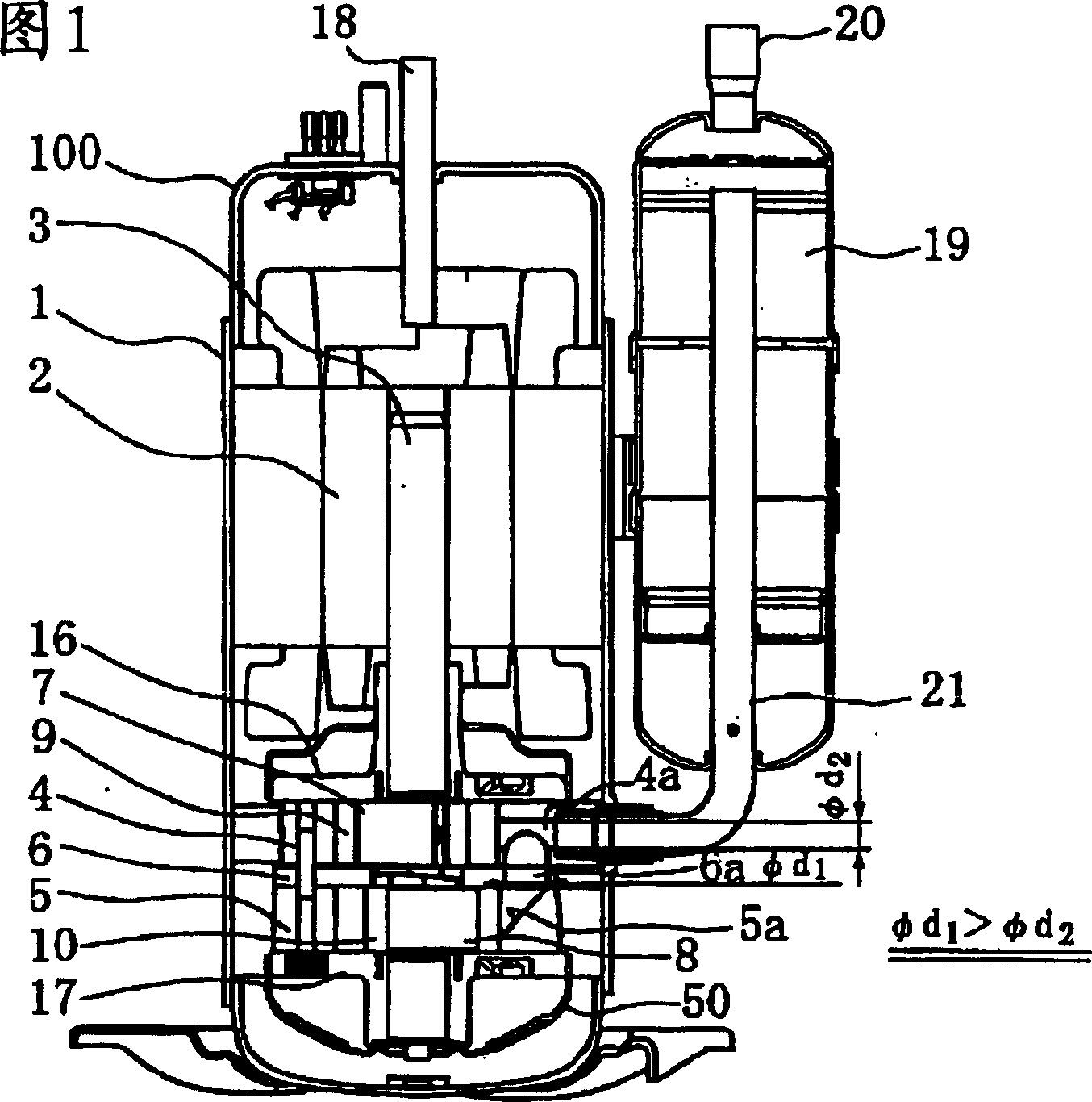
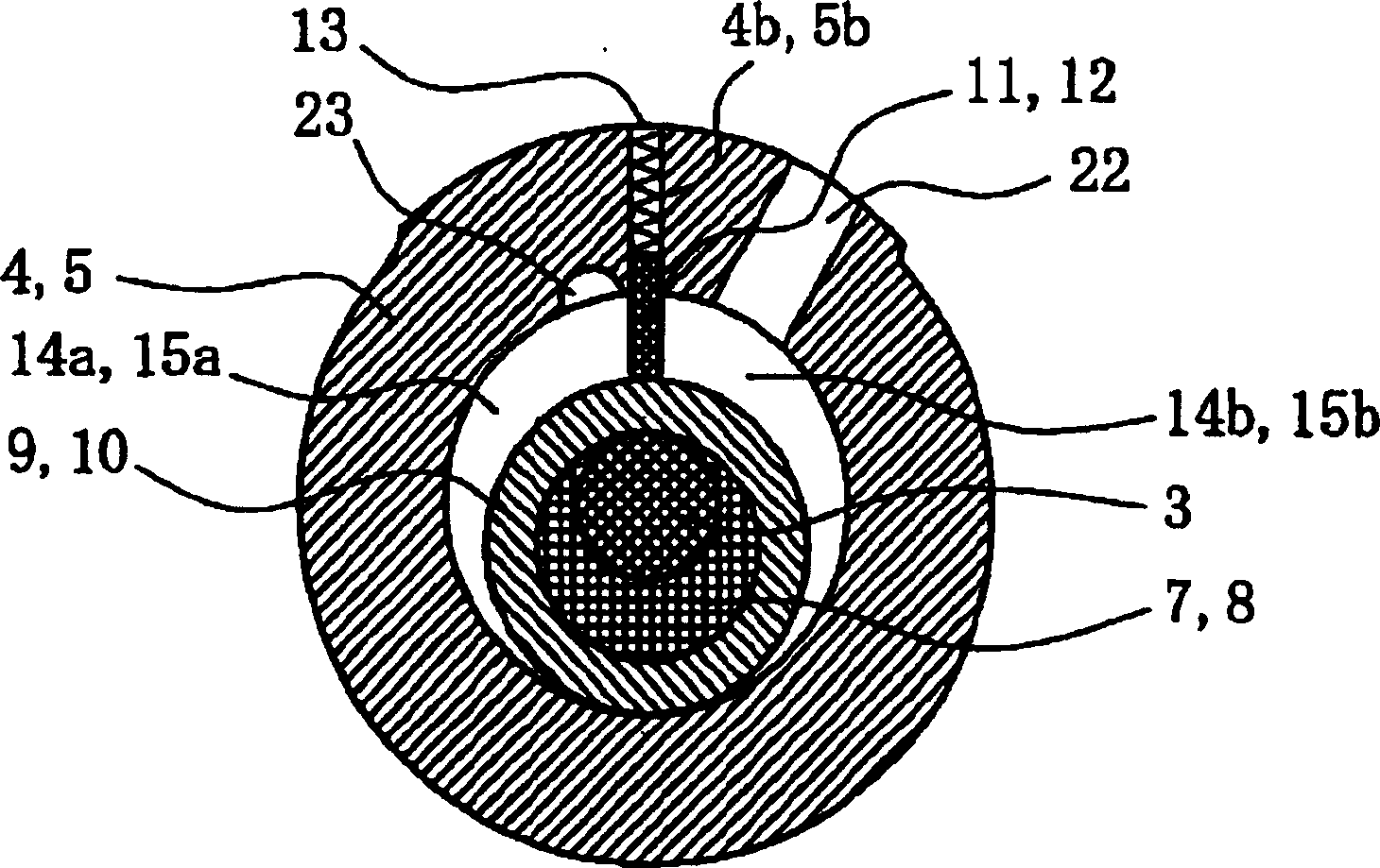
[0022] Hereinafter, embodiments of the present invention will be described with reference to the drawings. Fig. 1 is a longitudinal sectional view showing a double-cylinder hermetic rotary compressor according to Embodiment 1 of the present invention. and, figure 2 It is a cross-sectional view showing the compression chamber of the twin-cylinder hermetic rotary compressor according to Embodiment 1 of the present invention.
[0023] In the figure, the electric component 2 contained in the upper part of the airtight container 1 rotates the rotary pistons 9, 10 in the upper cylinder 4 and the lower cylinder 5 through the rotating shaft 3, the upper cylinder 4 is the first cylinder, and the lower cylinder 5 is the second cylinder. cylinder. Between the upper cylinder 4 as the 1st cylinder and the lower cylinder 5 as the 2nd cylinder, an intermediate partition 6 is set, and the opening end of the upper cylinder 4 as the 1st cylinder is closed with the main bearing 16 (for the up...
Embodiment approach 2
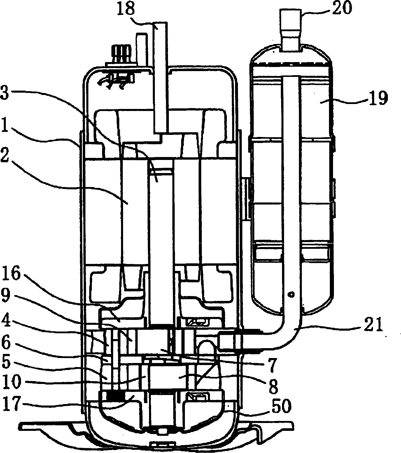
[0038] Next, a two-cylinder hermetic rotary compressor showing Embodiment 2 of the present invention will be described. image 3 It is a sectional view showing the compressor according to Embodiment 2 of the present invention. in addition, Figure 4 seen from another angle image 3 The longitudinal sectional view of the main part which shows the double-cylinder hermetic rotary compressor concerning Embodiment 2 of this invention is shown in . In the figure, and Embodiment 1 and Fig. 1, figure 2 The same symbols are attached to the same parts, and detailed explanations are omitted.
[0039] In this embodiment, the suction connection pipe 21 is only inserted into any one of the first cylinder or the second cylinder, and is provided in the branch flow channel 6a branching to the other cylinder in the cylinder to guide the refrigerant. One of the cylinders (such as the first cylinder) is provided with a spring 13, and the spring pushes the blade (such as the blade 11) to the ...
Embodiment approach 3
[0049] Next, a double-cylinder hermetic rotary compressor showing a third embodiment of the present invention will be described with reference to the drawings. Figure 5 It is a longitudinal sectional view showing the compressor according to Embodiment 3 of the present invention. In addition, FIG. 6 is a diagram for explaining the operation of the check valve provided on the branch channel, Figure 6a It is a diagram showing the operation of the check valve during normal rotation, Figure 6b It is a diagram showing the operation of the check valve when refrigerant gas and refrigerating machine oil return. In the drawings, the same parts as those in Embodiments 1 and 2 and FIGS. 1-4 are marked with the same symbols, and therefore description thereof will be omitted. In this embodiment, the suction connecting pipe is inserted into only one of the two (first and second) cylinders 4, 5 (for example, the first cylinder 4), and is installed in the cylinder to the other cylinder (for...
PUM
 Abstract
Description
Claims
Application Information
 - R&D
- Intellectual Property
- Life Sciences
- Materials
- Tech Scout
- Unparalleled Data Quality
- Higher Quality Content
- 60% Fewer Hallucinations
Browse by: Latest US Patents, China's latest patents, Technical Efficacy Thesaurus, Application Domain, Technology Topic, Popular Technical Reports.
© 2025 PatSnap. All rights reserved.Legal|Privacy policy|Modern Slavery Act Transparency Statement|Sitemap|About US| Contact US: help@patsnap.com