Method for producing workpiece
A manufacturing method and workpiece technology, which are applied in the field of workpiece manufacturing, can solve the problems that the machining precision cannot be accurately controlled, the concentricity error value is large, and the manufacturing cost is high, and the concentricity error is low, ensuring the stability and improving the service life. Effect
- Summary
- Abstract
- Description
- Claims
- Application Information
AI Technical Summary
Problems solved by technology
Method used
Image

Examples
Embodiment Construction
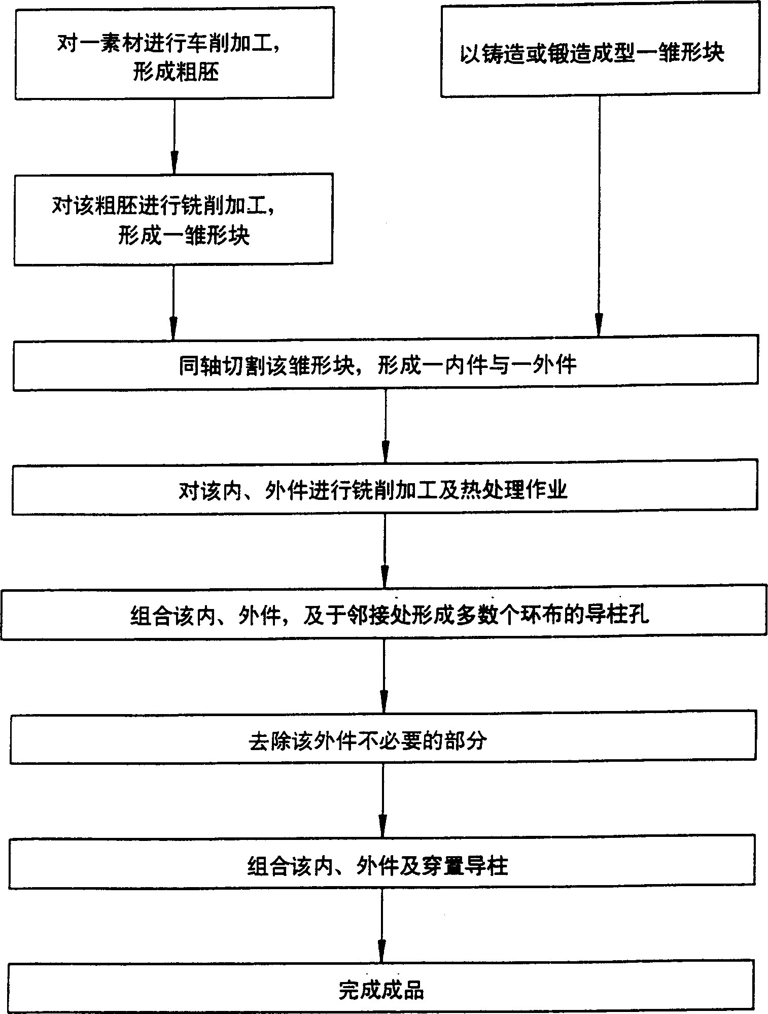
[0037] refer to figure 2 , the preferred embodiment of the manufacturing method of workpiece of the present invention comprises the following steps:
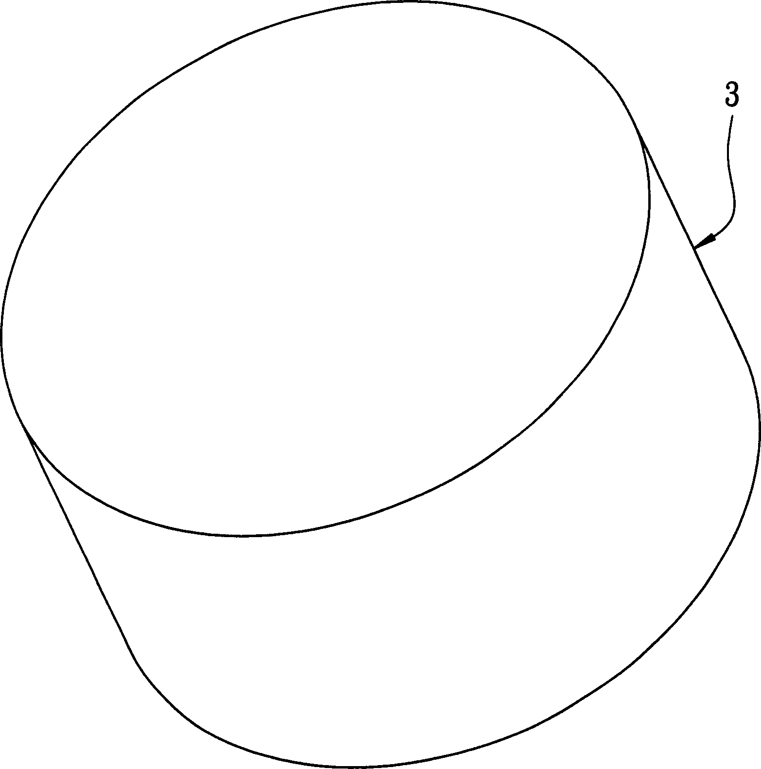
[0038] Step 1: Form a prototype block, see image 3 , Figure 4 , the forming method can be that a cylindrical material 3 is processed by turning to form a rough base 3', and then the rough base 3' is milled to form a rough base 3' such as Figure 5 Shown rudiment block 4, or directly in the mode of casting, forging, form as Figure 5 Prototype block 4 shown. The prototype block 4 has a first ring wall 41 and a second ring wall 42 surrounding an axis X and defining a small hole segment 401 and a large hole segment 402, and an inner surface formed on the first ring wall 41 And it is generally a C-shaped groove 45 . The diameter of the first ring wall 41 is larger than that of the second ring wall 42 . refer to Figure 6 , Then, the prototype block 4 is subjected to machining procedures such as drilling, tapping, and chamfe...
PUM
 Abstract
Description
Claims
Application Information
 - Generate Ideas
- Intellectual Property
- Life Sciences
- Materials
- Tech Scout
- Unparalleled Data Quality
- Higher Quality Content
- 60% Fewer Hallucinations
Browse by: Latest US Patents, China's latest patents, Technical Efficacy Thesaurus, Application Domain, Technology Topic, Popular Technical Reports.
© 2025 PatSnap. All rights reserved.Legal|Privacy policy|Modern Slavery Act Transparency Statement|Sitemap|About US| Contact US: help@patsnap.com