Umbrella structure constant force spring hanging frame

A constant force spring and hanger technology, applied in the direction of pipeline supports, pipes/pipe joints/pipes, mechanical equipment, etc., can solve the problems of large horizontal space occupation, product standardization, low degree of serialization, etc. Effect

Inactive Publication Date: 2005-08-03
毛学军
View PDF2 Cites 5 Cited by
  • Summary
  • Abstract
  • Description
  • Claims
  • Application Information

AI Technical Summary

Problems solved by technology

[0005] The purpose of the present invention is to provide a new type of constant force spring hanger with an umbrella structure in view of the relatively large horizontal space occupied by various types of constant force spring hangers at present, and the problems of product standardization and low serialization in US4006873A

Method used


Image

  • Umbrella structure constant force spring hanging frame
  • Umbrella structure constant force spring hanging frame
  • Umbrella structure constant force spring hanging frame

Examples


Embodiment Construction

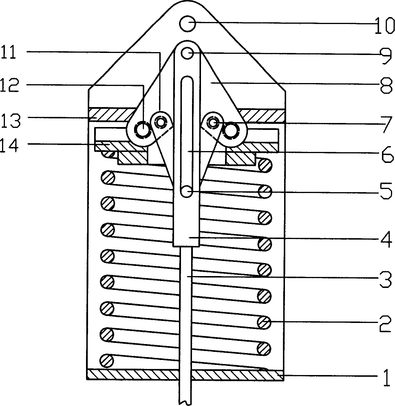
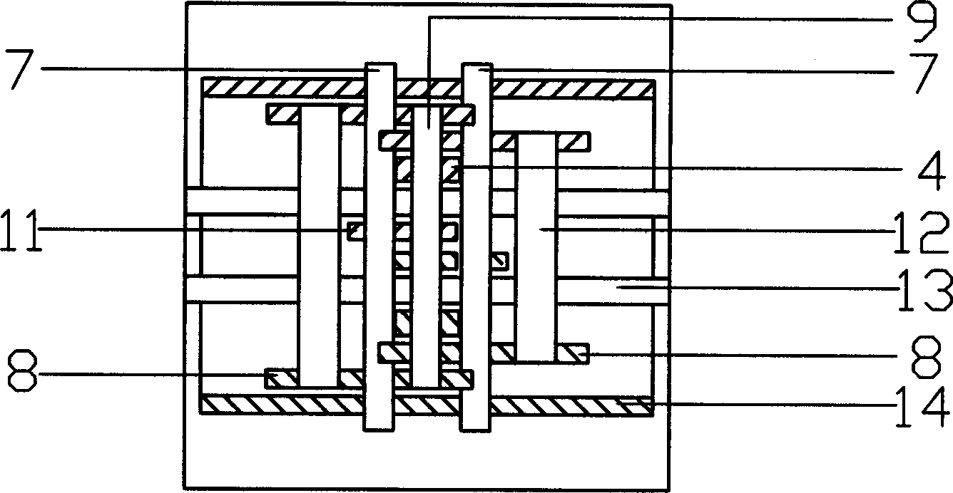
[0017] Working principle: when the load rod 3 bears the downward pulling force, the final shaft 7 bears the downward force, and the main shaft 12 bears the upward force. As the displacement of the load rod 3 changes, the spring 2 is under the action of the final shaft 7 and the pressure plate 14 When the elastic force changes, the center distance between the load rod 3, the final shaft 7 and the final shaft 7, and the main shaft 12 also changes correspondingly at the same time, so as to achieve the effect of moment balance.

[0018] Embodiments of the present invention will be further described below in conjunction with the accompanying drawings:

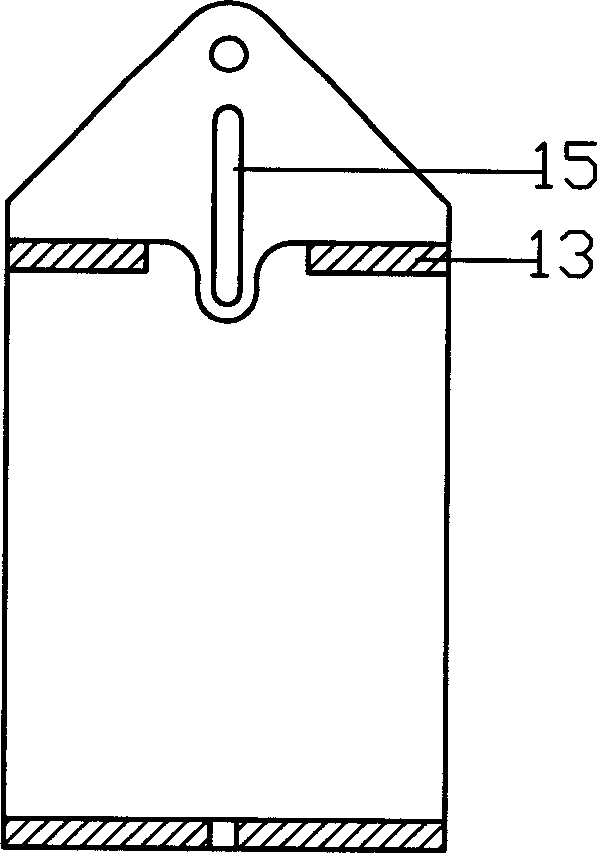
[0019] image 3 It is an overall view of the fixed frame 13 and the housing 1. There is a hole for the boom shaft 10 at the center of the upper part of the fixed frame 13. Below the center line of the hole is the load shaft slideway 15. There is a plane on both sides of the load shaft slideway 15. The main shaft 12 performs a horiz...


PUM


Abstract

The umbrella structure constant force spring hanging frame has novel design and may be used in a narrow space. The variable spring hanging frame in any required rigidity may be formed with standard springs, and product with vertical displacement and small load may be produced to meet the special requirement of contact network tension compensator in electric railway.

Description

technical field [0001] The invention relates to an umbrella structure design method applying the principle of moment balance, and is especially suitable for a vertical displacement constant force spring hanger used in a narrow space. Background technique [0002] The hanger is mainly used for suspension parts such as steam, water, smoke, wind, coal transmission pipes and burners of power plant boiler body and power plant, as well as other places where thermal stress caused by heat needs to be eliminated in petroleum, chemical and other places. [0003] At present, the constant force spring hangers for vertical displacement include German LESEG, the double-slewing frame disc spring hanger without spring pull rod 02138291.3, and the single boom self-adjusting center spring hanger 2004100656695, but the structure of these products takes up space in the horizontal direction The location is large, and the scope of application is limited. [0004] US4006873A constant force spring...

Claims


Application Information

Patent Timeline
Patent Type & Authority Applications(China)
IPC IPC(8): F16L3/21
Inventor 毛学军
Owner 毛学军
Why Eureka
Try Eureka