Telescoping dust collector suction pipe
A vacuum cleaner and telescopic technology, applied in the field of telescopic vacuum cleaner straws, can solve the problems of damage to the locking mechanism, low reliability of use, etc., and achieve the effects of enhancing the locking force, increasing the friction force, and reducing the probability of damage.
- Summary
- Abstract
- Description
- Claims
- Application Information
AI Technical Summary
Problems solved by technology
Method used
Image

Examples
Embodiment Construction
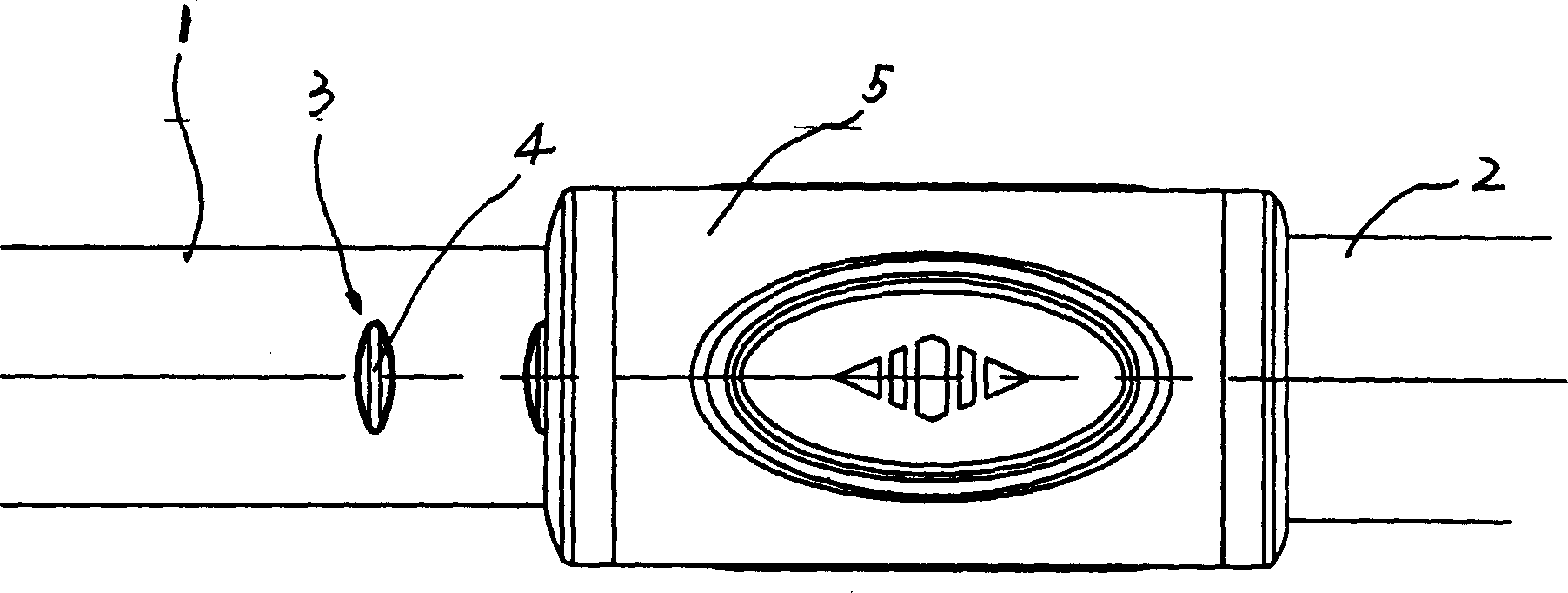
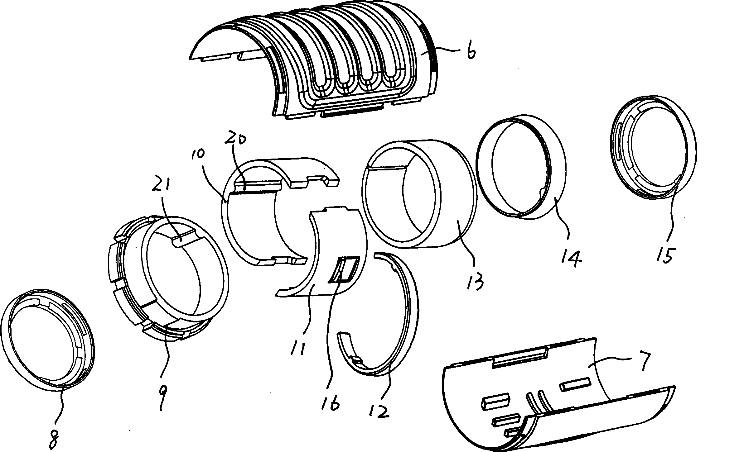
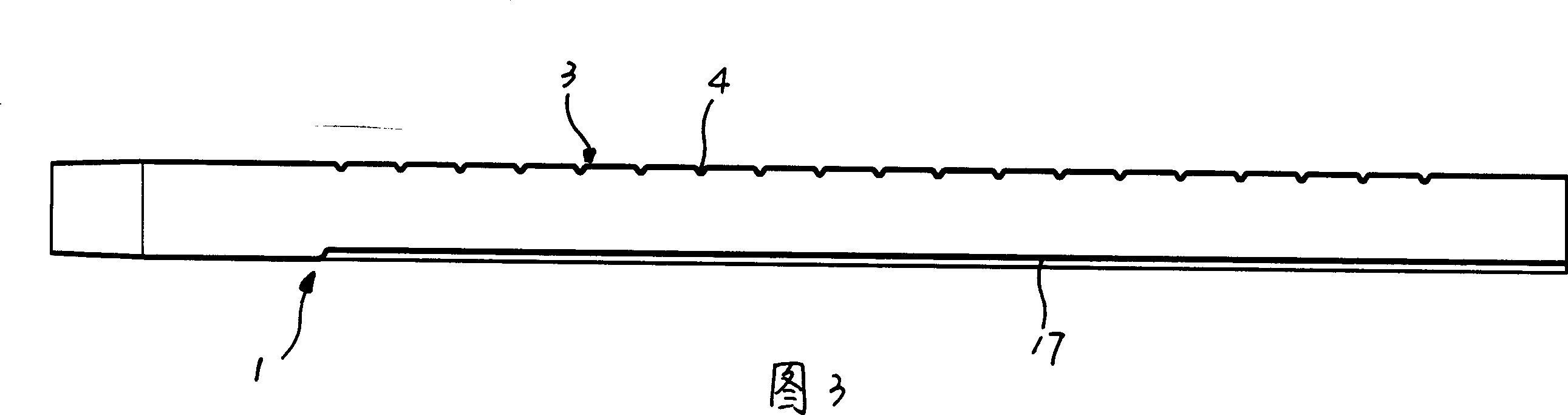
[0014] See attached figure 1 - Accompanying drawing 7, a suction pipe of a telescopic vacuum cleaner, comprising an outer pipe 2, an inner pipe 1 with a stop strip 3 extending axially, at least one locking member cooperating with the stop groove 4 of the stop strip 3 16. The inner tube 1 is slidably inserted into the outer tube 2, and a stop slider 11 is arranged between the outer tube 2 and the inner tube 1, and the stop slider 11 and the inner tube 1 The outer surfaces are in contact, and the locking member 16 is arranged on the stopping slider 11 . The outer tube 2 is slidably sleeved with a control sleeve 5, and the control sleeve 5 has at least one free space 22 for the displacement of the locking member 16, and the locking member 16 can break away from the stop groove 4 and Located in free space 22 .
[0015] See attached figure 2 , Accompanying drawing 4-accompanying drawing 7, described control sleeve 5 is provided with compression ring 12, and described control sl...
PUM
 Abstract
Description
Claims
Application Information
 - Generate Ideas
- Intellectual Property
- Life Sciences
- Materials
- Tech Scout
- Unparalleled Data Quality
- Higher Quality Content
- 60% Fewer Hallucinations
Browse by: Latest US Patents, China's latest patents, Technical Efficacy Thesaurus, Application Domain, Technology Topic, Popular Technical Reports.
© 2025 PatSnap. All rights reserved.Legal|Privacy policy|Modern Slavery Act Transparency Statement|Sitemap|About US| Contact US: help@patsnap.com