Airbag apparatus

An airbag and gas technology, which is used in transportation and packaging, pedestrian/occupant safety arrangement, vehicle safety arrangement, etc., can solve the problem of inability to control the internal pressure alone, and achieve the effect of improving the degree of freedom and reducing the number of parts

Inactive Publication Date: 2005-08-10
TAKATA CORPORATION
View PDF2 Cites 6 Cited by
  • Summary
  • Abstract
  • Description
  • Claims
  • Application Information

AI Technical Summary

Problems solved by technology

[0009] Although the above-mentioned conventional airbag device can control the expansion order of the centra

Method used


Image

  • Airbag apparatus
  • Airbag apparatus
  • Airbag apparatus

Examples


Example Embodiment

[0031] Hereinafter, embodiments of the present invention will be described with reference to the drawings.

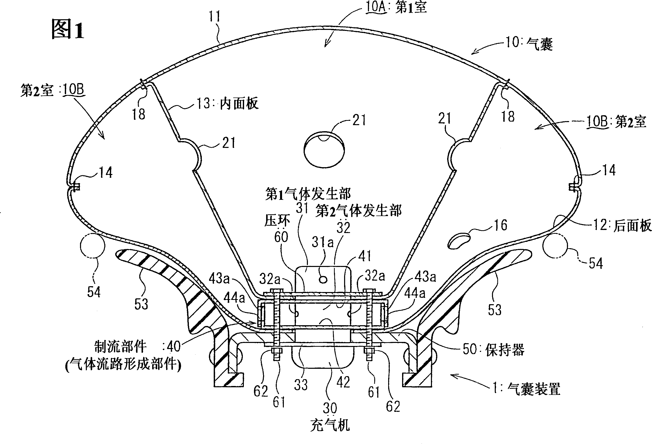
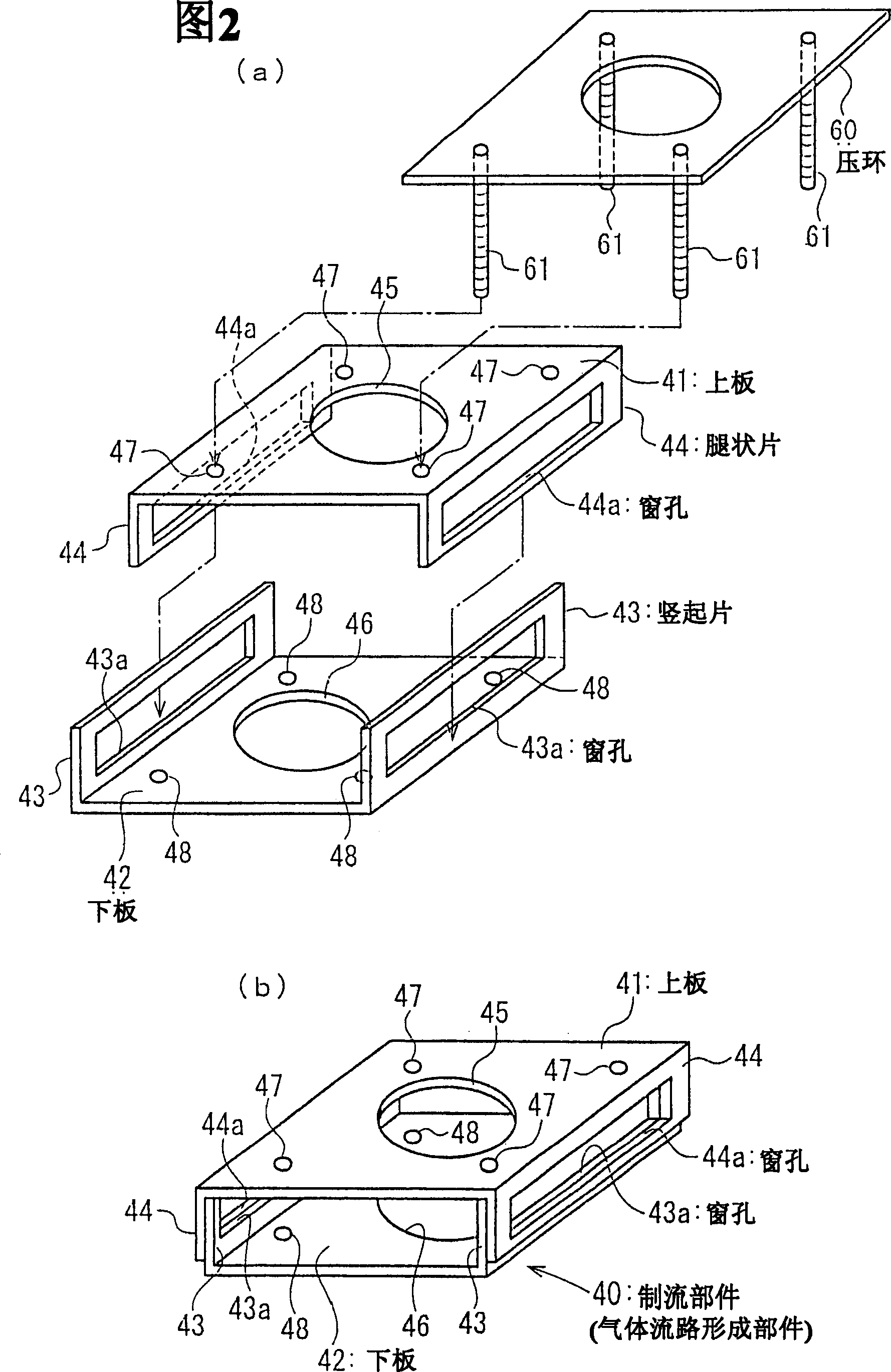
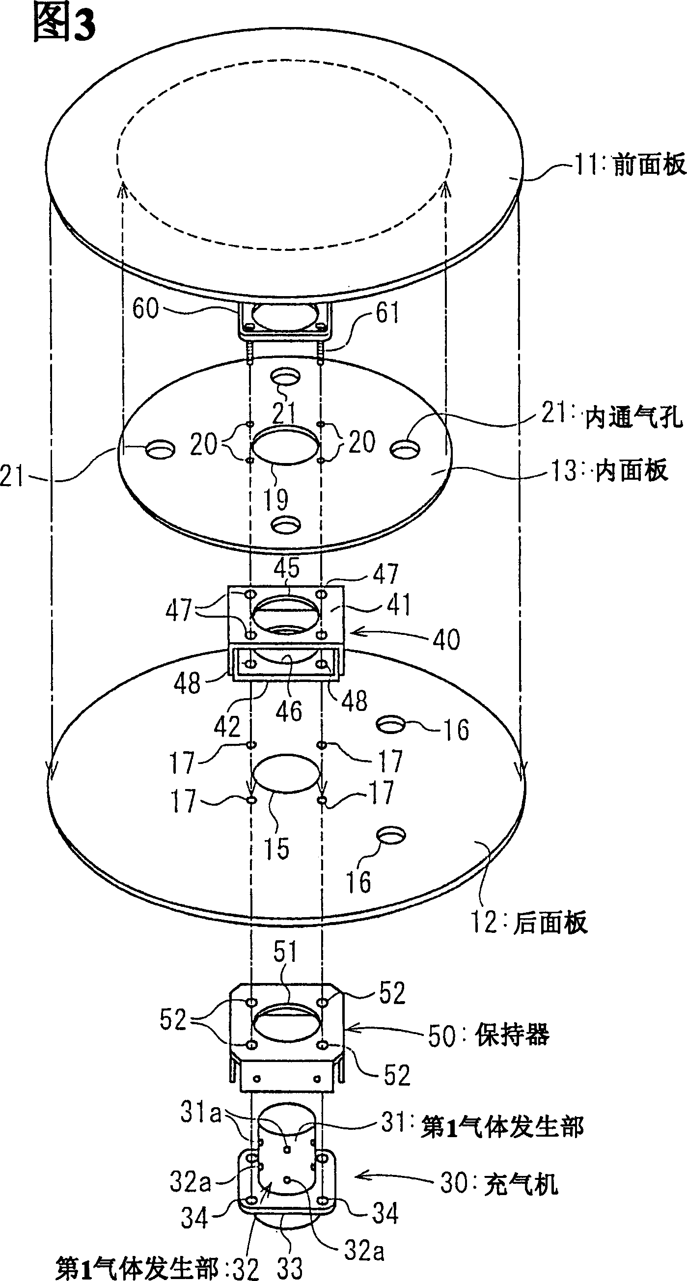
[0032] Fig. 1 is a longitudinal sectional view of an airbag device according to an embodiment, Fig. 2(a) is an exploded perspective view of a flow control member (gas flow path forming member) of the airbag device, and Fig. 2(b) is an assembled view of the flow control member Perspective view. Figure 3 is an exploded perspective view of the airbag device.

[0033] The airbag device 1 includes an airbag 10 partitioned into a first chamber 10A and a second chamber 10B, an inflator (gas generator) 30 that inflates the airbag 10, and gas generated by the inflator 30 flows into the first chamber 10A and 10B respectively. The flow control member (gas flow path forming member) 40 of the first chamber 10A and the second chamber 10B, the holder 50 to which the airbag 10, the inflator 30, and the flow control member 40 are mounted, and the like.

[0034] In this embodiment, the infla...


PUM


Abstract

To provide an airbag apparatus having an airbag provided with a plurality of chambers, or an airbag apparatus including a plurality of airbags, which can be configured in such a manner that not only the sequence of inflation of the respective chambers or the respective airbags, but also the internal pressure upon inflation can be controlled independently, an airbag apparatus (1) includes an airbag (10) having the interior being partitioned into a first chamber (10A) and a second chamber (10B), an inflator (30) for inflating the airbag (10), a flow control member (40) for allowing gas from the inflator (30) to flow independently into the first chamber (10A) and the second chamber (10B), and a retainer (50). The inflator (30) includes two gas generating units; a first gas generating unit (31) and a second gas generating unit (32), being capable of performing gas generating action independently, and the flow control member (40) allows gas from the first gas generating unit (31) to flow into the first chamber (10A) of the airbag (10), and gas from the second gas generating unit (32) to flow into the second chamber (10B).

Description

technical field [0001] The present invention relates to an airbag device installed in an automobile or the like. Background technique [0002] An airbag device installed in an automobile or the like includes an airbag and an inflator that inflates the airbag. [0003] If the collision of the vehicle is detected by the sensor, the inflator is activated, and the airbag is inflated by the gas generated by the inflator. [0004] JP-A-2-74440 discloses an airbag device that divides the inside of an airbag for the driver's seat into a central chamber and two chambers on the outer peripheral side with an isolation panel, first inflates the central chamber, and then inflates the outer peripheral chamber. chamber expansion. Vents for gas flow are provided on the isolation panel. The partition panel connects the rear side and the front side of the airbag, and has a function of preventing the airbag from protruding forward when inflated. [0005] In contrast, US Patent No. 6,254,12...

Claims


Application Information

Patent Timeline
IPC IPC(8): B60R21/16B60R21/217B60R21/233B60R21/26B60R21/263
CPCB60R2021/23324B60R2021/26058B60R2021/2633B60R21/261B60R21/217B60R21/233B60R21/26
Inventor 安部和宏妹尾里佳
Owner TAKATA CORPORATION
Why Eureka
Try Eureka