
Rotor blade for a rotary machine

A technology of rotor blades and rotating machines, applied in the direction of supporting elements of blades, mechanical equipment, engine elements, etc., to achieve the effect of reducing size and reducing the quality of the cover

Inactive Publication Date: 2005-08-10
UNITED TECH CORP
View PDF0 Cites 0 Cited by
  • Summary
  • Abstract
  • Description
  • Claims
  • Application Information

AI Technical Summary

Problems solved by technology

normal

Method used


Image

  • Rotor blade for a rotary machine
  • Rotor blade for a rotary machine
  • Rotor blade for a rotary machine

Examples


Embodiment Construction

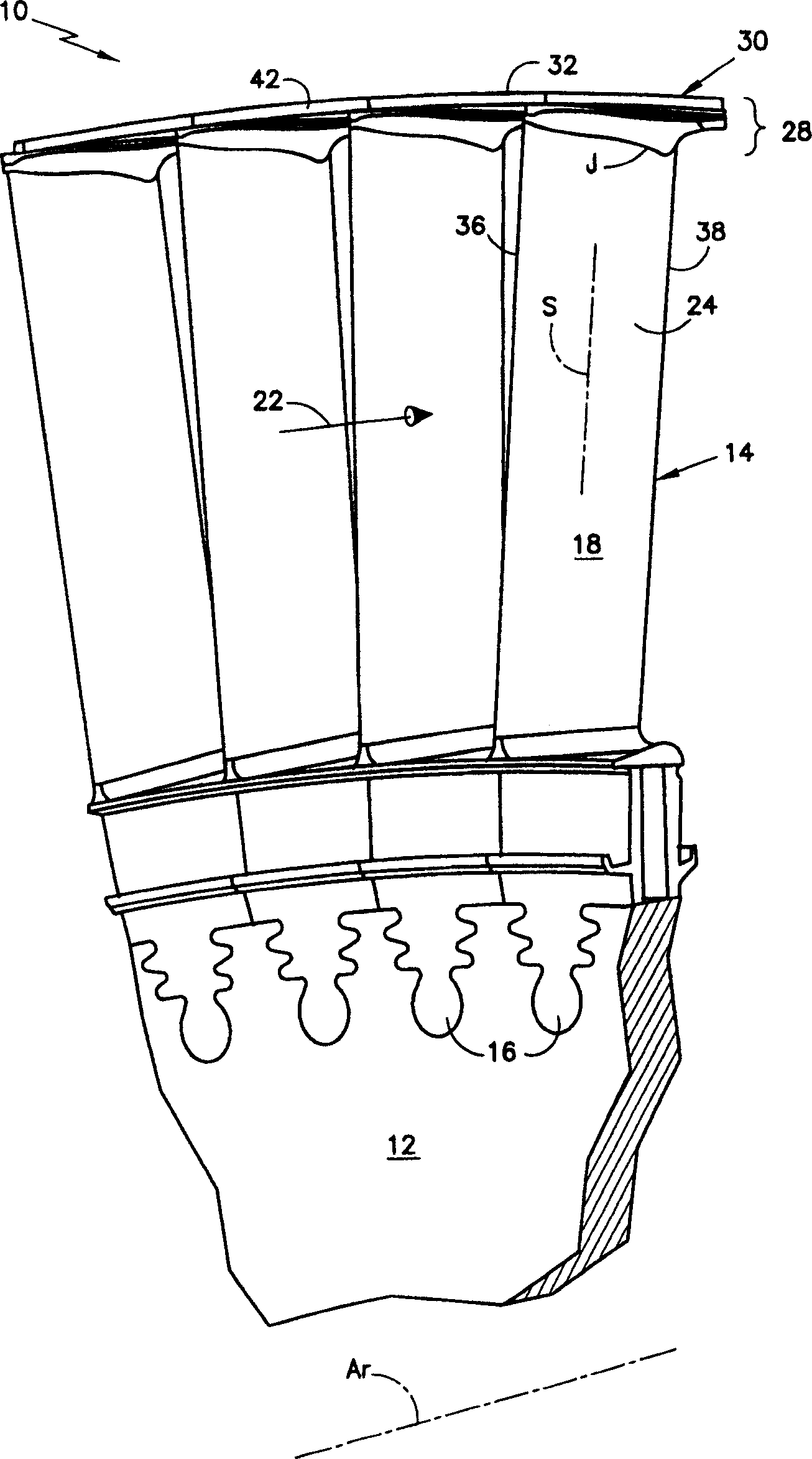
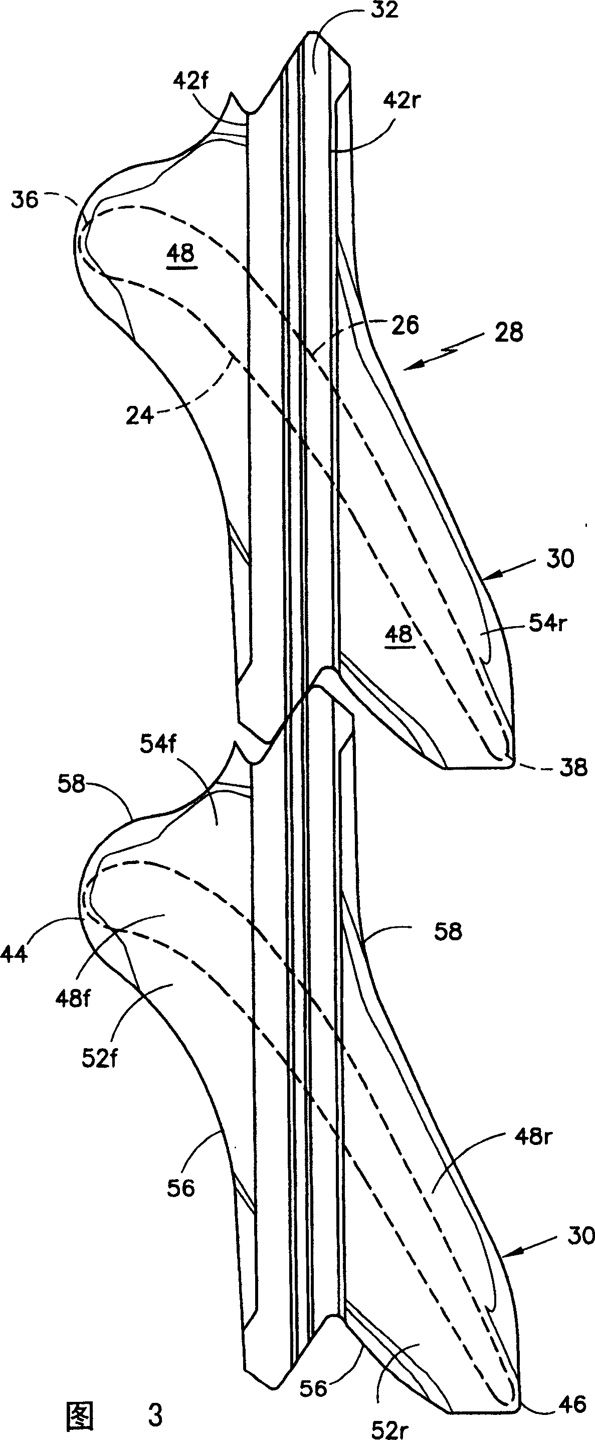
[0034] figure 1 is a simplified front elevation view of the rotor assembly 10 of the rotating machine with axis Ar. The rotor assembly includes a rotating structure as represented by a disk 12 , and a plurality of outwardly extending rotor blades 14 . Each rotor blade has a root 16 and an airfoil 18 disposed about a spanwise extending axis S commonly referred to as the stack line S. As shown in FIG. The airfoil has a pressure side 24 and a suction side 26 as shown in FIG. 3 . A flow path 22 for working medium gas extends through the rotor blade between the sides of the airfoil.

[0035] The rotor blade has a top region 28 with a top shroud 30 . The top cover comprises a sealing bead 32 which is a face with a radius of curvature around the axis Ar. The top shroud has a transition region 34 extending from the sides 24, 26 of the airfoil, as defined by figure 1 , Figure 4 and Figure 5 The pressure side 24 shown in; and the suction side 26 shown in Figures 4 and 6 represent...


PUM


Abstract

A rotor blade (14) having a wing (52,54) and beam (42) construction for a tip shroud (30) is disclosed. Various construction details are developed for providing the shroud with a depression (48) in the shroud (30) and a transition zone (34) that extends from the suction side (26) and pressure side (24) of the airfoil to provide a flow path surface of the shroud. In one detailed embodiment, the tip shroud has a depression (48) generally outwardly of the airfoil and generally following the curve of the pressure and suction sides (24,26) of the airfoil from the leading edge region (36) to the trailing edge region (38).

Description

technical field [0001] The present invention relates to rotor blades of the type used in industrial gas turbines, and more particularly to the tip region of such rotor blades. Background technique [0002] Aircraft gas turbines have generally smaller rotor blades than those used, for example, in the turbines of industrial gas turbines using steam as the working medium. [0003] Rotor assemblies utilize such blades, such as rotor disks, having a rotating structure including an axis of rotation and a plurality of outwardly extending blades. Each blade is disposed about a radially extending spanwise axis. Typically, the spanwise axis is a radial line called the stack line, which extends outward on a radius of the axis of the rotor blade. A rotor blade has a base, often referred to as a root, which engages the rotating structure at the inner end of the blade. [0004] The rotor blades each have an airfoil extending outwardly from the root across the working medium flow path. ...

Claims


Application Information

Patent Timeline
IPC IPC(8): F01D5/14F01D5/22
CPCF05D2250/70Y02T50/671F01D5/225F01D5/147Y02T50/673F05B2250/70Y02T50/60
Inventor B·P·杜布E·D·格雷
Owner UNITED TECH CORP
Learn More