Check patentability & draft patents in minutes with Patsnap Eureka AI!

Optical projection system and method

A technology of optical projection and projection, which is applied in the field of optical projection systems, can solve the problems that it is not easy to achieve equal optical paths, and cannot be adjusted arbitrarily.

Inactive Publication Date: 2005-08-24
UNITED MICROELECTRONICS CORP
View PDF0 Cites 3 Cited by
  • Summary
  • Abstract
  • Description
  • Claims
  • Application Information

AI Technical Summary

Problems solved by technology

And because it is a non-telecentric design, the optical path of each color beam is limited by the color beam splitter and cannot be adjusted arbitrarily, so the optical path of each color beam is not easy to achieve the design of equal optical path

Method used


Image

  • Optical projection system and method
  • Optical projection system and method
  • Optical projection system and method

Examples


Embodiment Construction

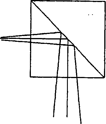
[0042] For the above Figure 4 The traditional design of the present invention finds through the analysis of the present invention, and it also has many problems. For example, if the wire-grid polarizer 320 is bent due to non-uniform thermal expansion or other reasons, the light beams will be reflected non-parallel, resulting in severe lateral color or transverse dichromatic aberration.

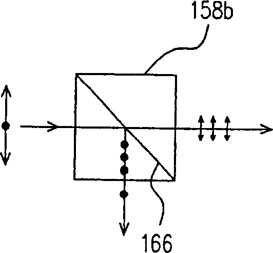
[0043] For the wire-grid polarizer 320, in conjunction with the operation of the reflective liquid crystal panel 322 and the light-combining prism 162, the traditional basic operating mechanism is as follows: Figure 5 shown. The light passing through the wire grid polarizer has a polarization state and reaches the reflective liquid crystal panel 322 . The reflective liquid crystal panel 322 converts the polarization state to another polarization state according to the needs of each pixel, and then reflects to the wire grid polarizer. Then, due to the characteristics of the wire-grid polar...


PUM


Abstract

This invention relates to an optics projection system and method, which can receive red beam, green beam and blue beam. The projection system includes a combining optical prism, and these beams go into the prism from three faces, and a combining beam goes out from the other face. A projection lens group receives the combining beam. As to every beam it includes a reflecting LCD face plate and a polar light component, and the LCD face plate parallels the faces of the combining optical prism. Thereafter, before these beams go into the combining optical prism, firstly the polar light component reflects to the LCD face plate, and the LCD face plate reflects these beams and makes the polar light component directly go into the combining optical prism.

Description

technical field [0001] The present invention relates to an optical projection system, and in particular to a wire grid polarizing element capable of combining light in a transmissive manner. Background technique [0002] Optical projection systems are very common in daily life. For example, a tiny image data is projected onto a large screen for users to watch. In particular, when other technologies are significantly developed, such as the development of liquid crystal display technology, combined with an optical projection system, the effect of displaying images can be achieved. For example, LCD projection TV is a modern technology product. [0003] For optical projection systems, with the use of liquid crystal display elements, traditional system designs such as figure 1 shown. figure 1 The conventional optical projection system is designed by utilizing the characteristics of a polarization beamsplitter (PBS). A light beam 100 first enters a color beam splitter 150 to s...

Claims


Application Information

Patent Timeline
Patent Type & Authority Applications(China)
IPC IPC(8): G02B5/00G02B27/18G02F1/133
Inventor 吕和陈中荣叶世博
Owner UNITED MICROELECTRONICS CORP
Features
  • R&D
  • Intellectual Property
  • Life Sciences
  • Materials
  • Tech Scout
  • Unparalleled Data Quality
  • Higher Quality Content
  • 60% Fewer Hallucinations
Learn More