System and method for inspecting a beam using micro fiber-optic technology

A fiber-optic, miniature technology, applied to inspect the hidden surface in the beam, inspect the surface of the beam, and can solve the problem of high cost

Inactive Publication Date: 2005-08-31
THE BOEING CO
View PDF0 Cites 3 Cited by
  • Summary
  • Abstract
  • Description
  • Claims
  • Application Information

AI Technical Summary

Problems solved by technology

On average, removing a galley, picking up the floor paneling, inspecting the beams, replacing the beams or treating them with an anti-corrosion compound, and then replacing the floor and galley again requires each galley (or Lavatory, etc.) 600+ man-hours, thus making this inspection / repair process very costly

Method used


Image

  • System and method for inspecting a beam using micro fiber-optic technology
  • System and method for inspecting a beam using micro fiber-optic technology
  • System and method for inspecting a beam using micro fiber-optic technology

Examples


Embodiment Construction

[0014] Although the preferred embodiment is described below with regard to inspecting the floor beams of an aircraft, the invention should not be so narrowly understood or restricted to use only on aircraft. It is contemplated that the present invention is applicable to inspecting the concealed surface of any beam, whether in an aircraft, bus, ship, building or any other structure.

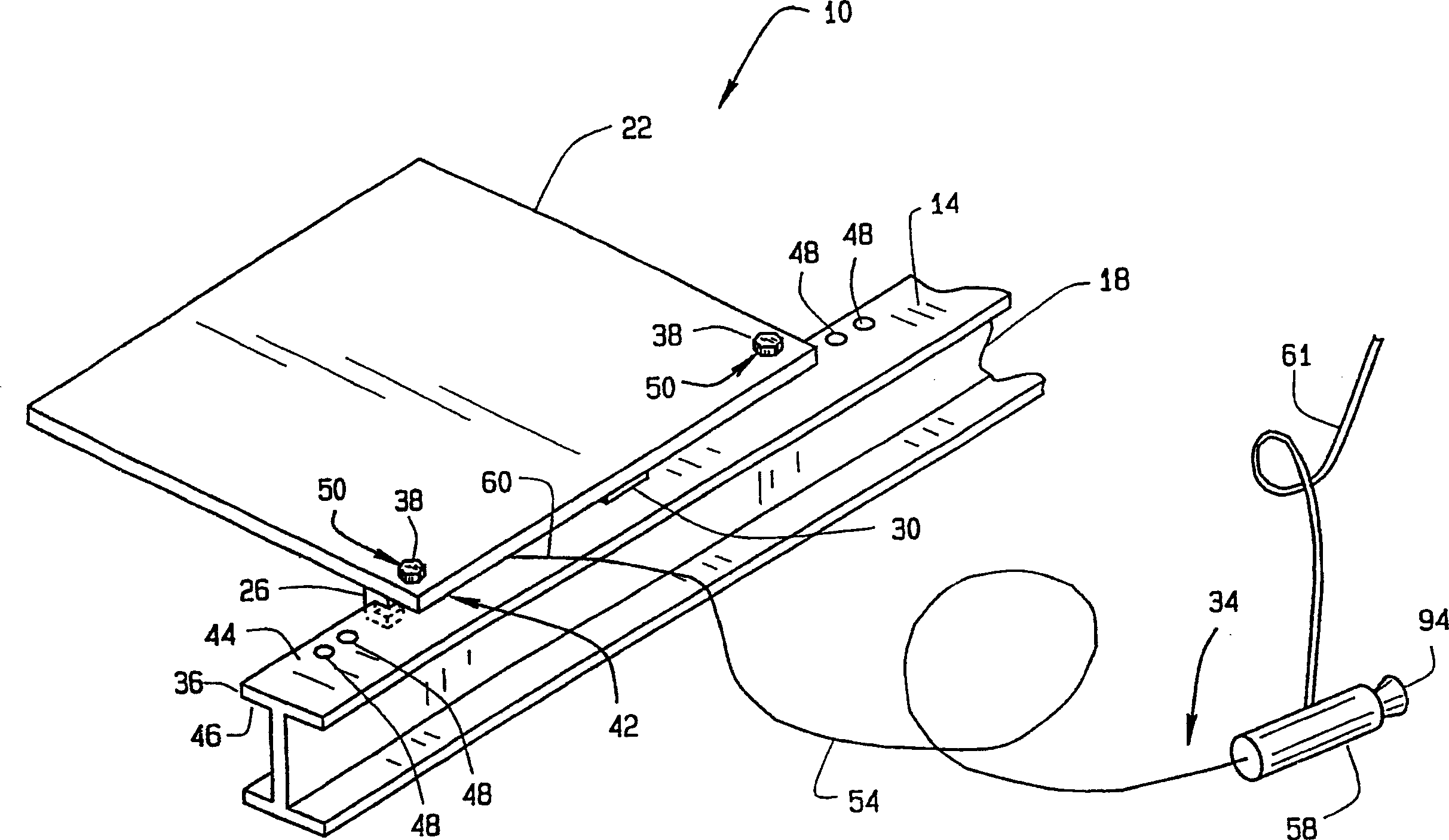
[0015] figure 1 is a perspective view of a system 10 for inspecting the upper surface 14 of a floor beam 18 covered by a floor panel 22 in accordance with a preferred embodiment of the present invention. The term "floor beam" is intended to include any beam or member used to support the floor panel 22, for example, in aircraft terms the term "floor beam" includes aircraft seat rails.

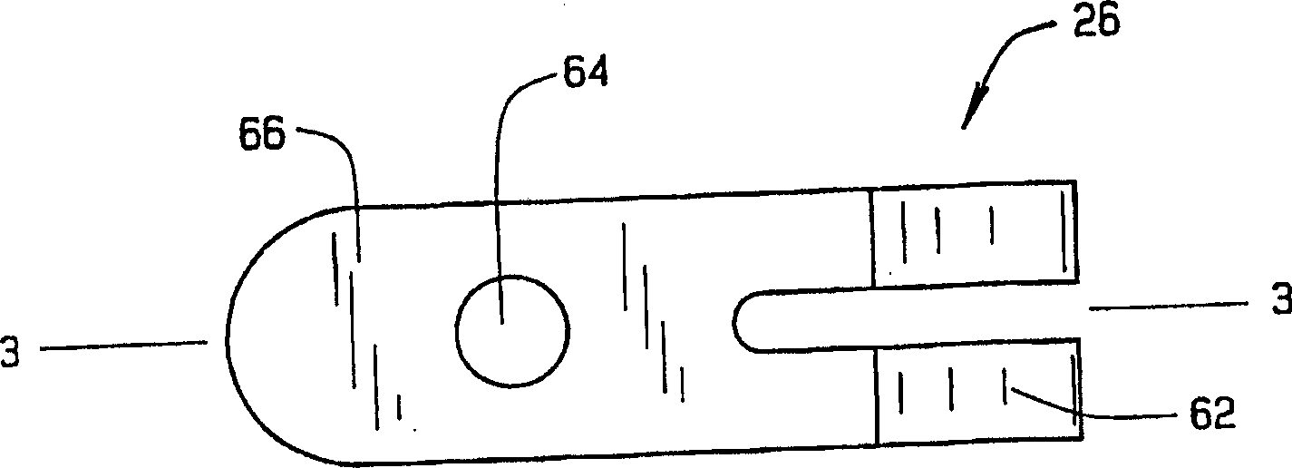
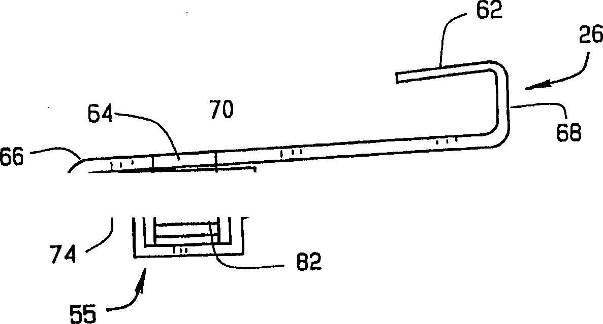
[0016] The inspection system 10 includes at least one nut clamp 26 , at least one spacer 30 and a miniature fiber optic borescope 34 . The nut clips 26 are mounted to the floor rail flanges 36 and the floor panels...


PUM


Abstract

A system for inspecting a surface of a beam covered by at least one structure. The system includes at least one nut clip attached to the beam used to couple the structure to the beam, and at least one spacer inserted between the beam and the structure for creating a gap between the structure and the beam. A micro fiber-optic borescope is used to view the surface of the beam covered by the structure without removing the structure. The surface is viewed by inserting a micro fiber-optic thread of the borescope into the gap. The system eliminates the need for costly and time consuming disassembly and removal of components mounted on the structure before an inspection of the condition of the beam can be made.

Description

technical field [0001] The present invention relates generally to microfiber optic technology for inspecting beam surfaces. In particular, the invention relates to the inspection of hidden surfaces in beams by inserting the miniature fiber optic filaments of a miniature fiber optic borescope between the beam and a structure obscuring said surfaces. Background technique [0002] Inspection of beams, such as floor beams of aircraft, for corrosion and / or cracks typically requires removal of any structure mounted on the beams, such as floor panels. If a complex structure such as an aircraft lavatory is installed on a beam, it is very difficult, laborious and costly to remove this structure in order to inspect hidden surfaces in the beam. [0003] For example, maintenance programs for commercial airline aircraft typically require heavy maintenance inspections every 5 to 7 years. The floor structure is inspected for corrosion damage by completely removing any structure fitted to...

Claims


Application Information

Patent Timeline
Patent Type & Authority Applications(China)
IPC IPC(8): G01N21/88G01N21/954
CPCG01N21/8803G01N2021/9546
Inventor 约瑟夫·F·弗洛伊德约翰·R·林
Owner THE BOEING CO
Why Eureka
Try Eureka