
Apparatus for automatically arranging casings and loading casings into hanger

A technology of automatic arrangement and shell parts, applied in the direction of spraying device, device for coating liquid on the surface, coating, etc., can solve the problems of poor effect and inconvenient design

Inactive Publication Date: 2005-09-07
王树生
View PDF0 Cites 2 Cited by
  • Summary
  • Abstract
  • Description
  • Claims
  • Application Information

AI Technical Summary

Problems solved by technology

[0002] In the prior art, the shells are individually arranged and loaded into the sling, and the conveying speed of the conveyor is the time t required for each shell, then the action beat of the ejection mechanism is t, and the action beat of the arrangement and dropping device is t. It can only be implemented by using a complex mechanism running at high speed, which brings a lot of inconvenience to the design, and the effect is also extremely poor

Method used


Image

  • Apparatus for automatically arranging casings and loading casings into hanger

Examples


Embodiment Construction

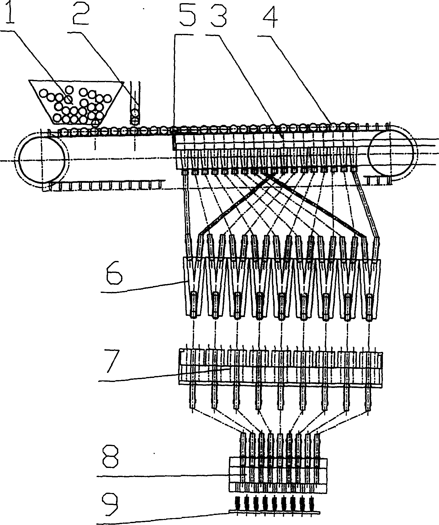
[0006] Control attached picture , its structure is that the upper part device 1 and the supplementary part device 2 are above the beginning end of the conveying line 3, the shell parts 4 are evenly arranged on the front end of the conveying line 3, and the ejection mechanism 5 is on the tail end of the conveying line 3, two in one The device 6 communicates with the corresponding holes in the ejection mechanism 5 through pipelines under the ejection mechanism 5. The dispersion device 7 is located below the two-in-one device 6, and the hole at the bottom of the two-in-one device 6 is connected to the upper part of the dispersion device 7 through the pipeline. Corresponding holes are communicated, and hanger 9 is positioned at the below that arranges and drops device 8.

[0007] work process:

[0008] The shell parts 4 are evenly distributed on the conveying line 3 through the loading device 1 and the replenishing device 2 . The head and tail of the shell 4 may be in two direct...


PUM


Abstract

The invention is the equipment of shells automatic arranging and loading into the spreader. The uplift equipment and the filling equipment are above on the starting end of transition line. The shells evenly arrange at the front end of the transition line. The pushing-out apparatus is on the back end of the transition line. The diad equipment is under the pushing-out apparatus and is linked to the corresponding hole in the pushing-out apparatus through the channel. The dispersing equipment is under the diad equipment, and the channel makes the lower holes of the diad equipment communicate with the corresponding holes of the dispersing apparatus. The spreader is under the arranging spreading equipment. The strong points of the invention rely in: the pushing-out apparatus and the diad equipment evenly separate the shells transmitted by the transition line to N rows, and the dispersing equipment separates each row into M circuits and the spreader has MxN needles. The said shells are set on the spreader. The time of each shell transition is t, and the time of the pushing-out apparatus is t.N, and the time of the arranging spreader is t.M.N. The design of the invention is convenient and the simple low-speed apparatus can operate.

Description

technical field [0001] The invention relates to a device for automatically arranging and loading shell parts into a sling on a small shell-shaped tool coating production line. It belongs to the technical field of logistics transportation and coating. Background technique [0002] In the prior art, the shells are individually arranged and loaded into the sling, and the conveying speed of the conveyor is the time t required for each shell, then the action beat of the ejection mechanism is t, and the action beat of the arrangement and dropping device is t. Must adopt the complex mechanism of high-speed operation just can implement, this has brought a lot of inconvenience to the design, and effect is also extremely poor. Contents of the invention [0003] The object of the present invention is to aim at the defects of the above-mentioned existence, and propose a kind of shell parts that can be automatically arranged and loaded into the sling and adopt the simple mechanism of ...

Claims


Application Information

Patent Timeline
IPC IPC(8): B05B13/02B05C13/00
Inventor 王树生
Owner 王树生
Learn More