Method and device for testing deep of film

A technique for measuring devices and measuring methods, which is applied in the direction of measuring devices, optical devices, chemical instruments and methods, etc., can solve the problems of narrowness, low reflectivity, and decreased reliability of film thickness measurement, and achieve the elimination of deviation and film thickness measurement. Effect of Accuracy Improvement

Inactive Publication Date: 2005-09-07
DAINIPPON SCREEN MTG CO LTD
View PDF1 Cites 28 Cited by
  • Summary
  • Abstract
  • Description
  • Claims
  • Application Information

AI Technical Summary

Problems solved by technology

On the other hand, since the reflectance is lower than the theoretical value in the wavelength region of the slope of the transmittance curve, the reliability of film thickness measurement will be significantly reduced when this wavelength region is included in the measurement wavelength region.
[0008] Therefore, it can be considered that by taking only the wavelength range other than the wavelength region of the slope portion in the transmittance curve, that is, as Figure 9 In this way, the wavelength region at the top horizontal part of the transmi

Method used


Image

  • Method and device for testing deep of film
  • Method and device for testing deep of film
  • Method and device for testing deep of film

Examples


no. 1 approach

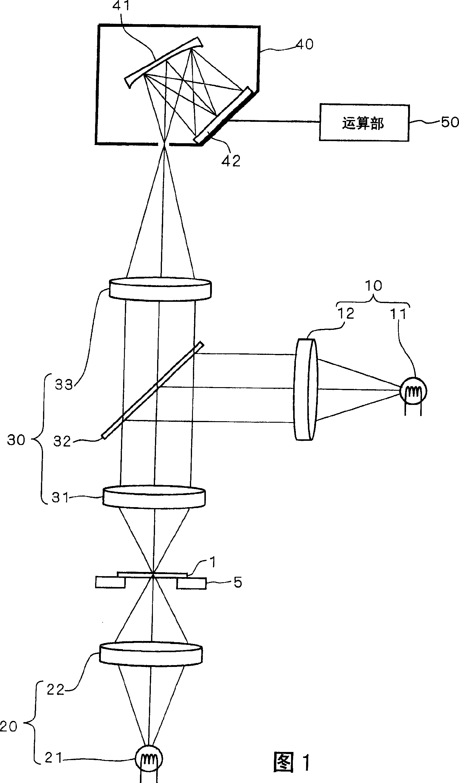
[0042] FIG. 1 is a view showing the structure of a film thickness measuring device of the present invention. The film thickness measurement device includes: a first illumination optical system 10 , a second illumination optical system 20 , and an imaging optical system 30 . The first illumination optical system 10 includes a halogen lamp 11 that emits white light and an illumination lens 12 . The illumination lens 12 is constituted by, for example, a combination of condensing lenses, and a field stop (not shown) and the like are attached to the condensing lenses. Light emitted from the halogen lamp 11 enters the imaging optical system 30 through the illumination lens 12 .

[0043] The imaging optical system 30 is composed of an objective lens 31 , a half mirror 32 and an imaging lens 33 . The illumination light from the first illumination optical system 10 is reflected by the half mirror 32 and irradiates the upper surface of the sample 1 placed on the sample stage 5 through...

no. 2 approach

[0077] Next, a second embodiment of the present invention will be described. The device structure of the film thickness measuring device of the second embodiment is the same as that of Fig. 1, figure 2 As in the first embodiment shown, the processing procedure of the film thickness measuring method is also substantially the same as in the first embodiment. The difference between the second embodiment and the first embodiment is that when calculating the film thickness of the color filter, the difference between the theoretical spectral reflectance and the measured spectral reflectance is weighted corresponding to the spectral transmittance.

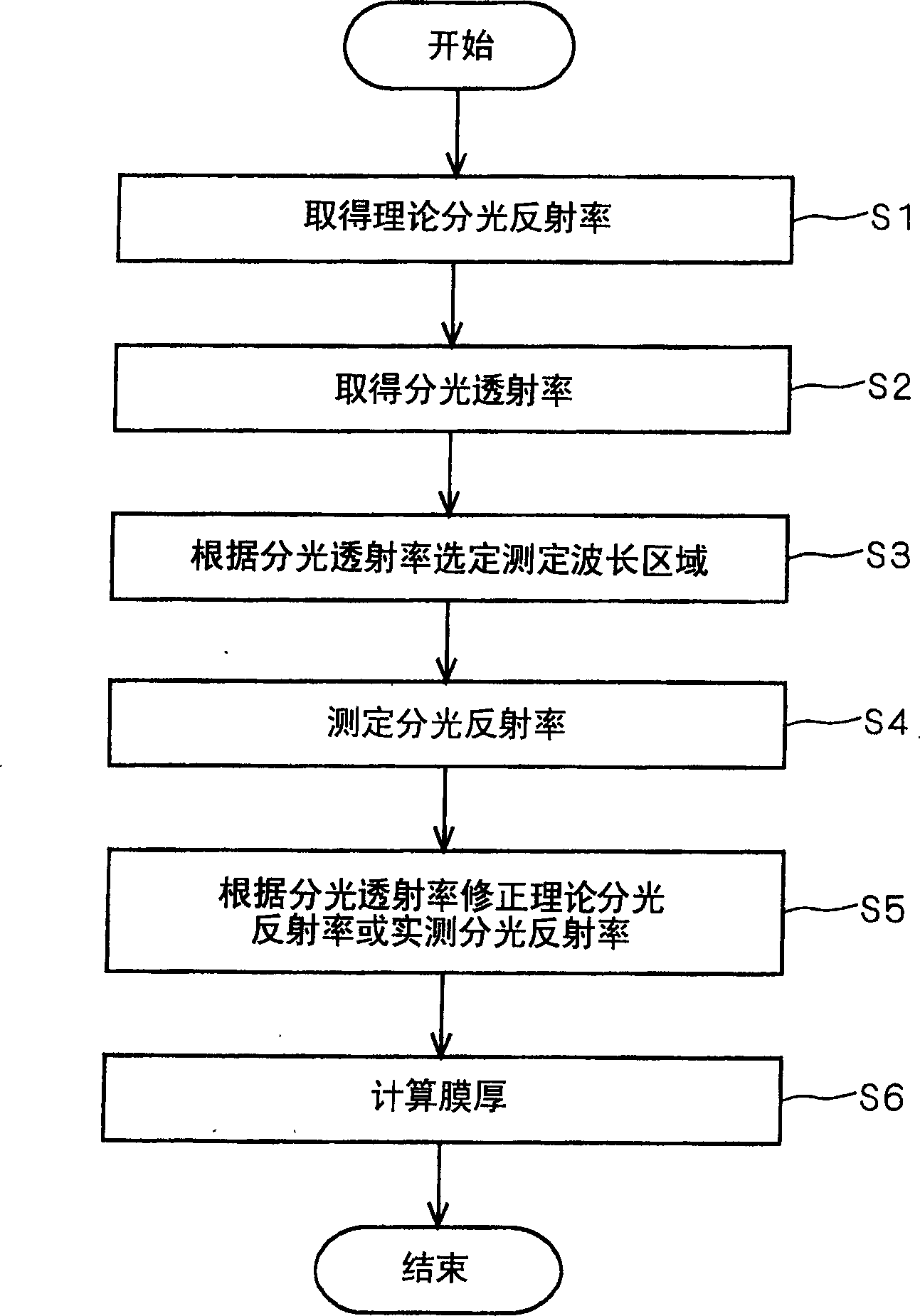
[0078] In the second embodiment, when measuring the film thickness of the color filter, the above-mentioned image 3 Steps S1 to S5 are exactly the same processing. Then proceed to step S6, and the film thickness calculation unit 56 calculates the film thickness of the color filter to be measured by comparing the corrected theoretical ...


PUM


Abstract

The invention provides a film thickness measurement technique which correctly measures film thickness even for a transparent film which selectively transmits light of specific wavelength ranges such as a color filter.Theoretical spectral reflectance calculated as the spectral reflectance of a sample, in which a colorless transparent film having predetermined film thickness is formed on a substrate, is acquired a plurality of times for different film thickness. The spectral transmittance of a color filter, which is an object to be measured, is acquired. Concerning the spectral transmittance, a wavelength range providing transmittance of a predetermined value or more is selected as a measurement wavelength range. A plurality of theoretical spectral reflectance calculated for different film thickness are corrected by the spectral transmittance to determine corrected theoretical spectral reflectance. A sample, in which the color filter is formed on a substrate, is irradiated with light, and reflected light from the sample is spectrally separated to measure the spectral reflectance. The measured spectral reflectance is compared to the corrected theoretical spectral reflectance to calculate the film thickness of the color filter.

Description

technical field [0001] The present invention relates to a film for measuring the film thickness of a transparent thin film formed on a substrate such as a semiconductor substrate or a glass substrate for a liquid crystal display, especially a transparent thin film such as a color filter that selectively transmits light in a specific wavelength range Thickness measurement method and device. Background technique [0002] In the past, for example, in Japanese Patent Laid-Open Publication No. 6-249620 (1994), it has been proposed to measure the film thickness of an extremely thin transparent film such as a resist film or a silicon oxide film formed on such a substrate by using an optical interference method. Technology. In the film thickness measurement using the optical interference method, under the condition that light is incident on a substrate on which a transparent thin film having a film thickness of a predetermined value d is formed, the spectral reflectance specified b...

Claims


Application Information

Patent Timeline
IPC IPC(8): G01B11/06
CPCC01B13/11C01B2201/22C01B2201/24C01B2201/62C01B2201/64
Inventor 藤原成章
Owner DAINIPPON SCREEN MTG CO LTD
Why Eureka
Try Eureka