Bicycle driving chain

A technology for driving chains and bicycles, applied in transmission chains, vehicle parts, vehicle gearboxes, etc., to simplify the installation of chains

Inactive Publication Date: 2005-09-14
SRAM
View PDF2 Cites 8 Cited by
  • Summary
  • Abstract
  • Description
  • Claims
  • Application Information

AI Technical Summary

Problems solved by technology

Multiple chain rollers surround these pins

Method used


Image

  • Bicycle driving chain
  • Bicycle driving chain
  • Bicycle driving chain

Examples


Embodiment Construction

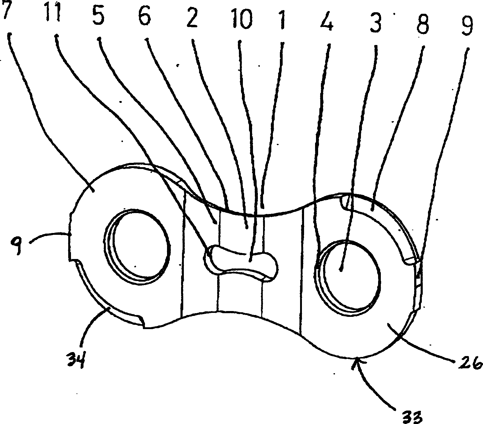
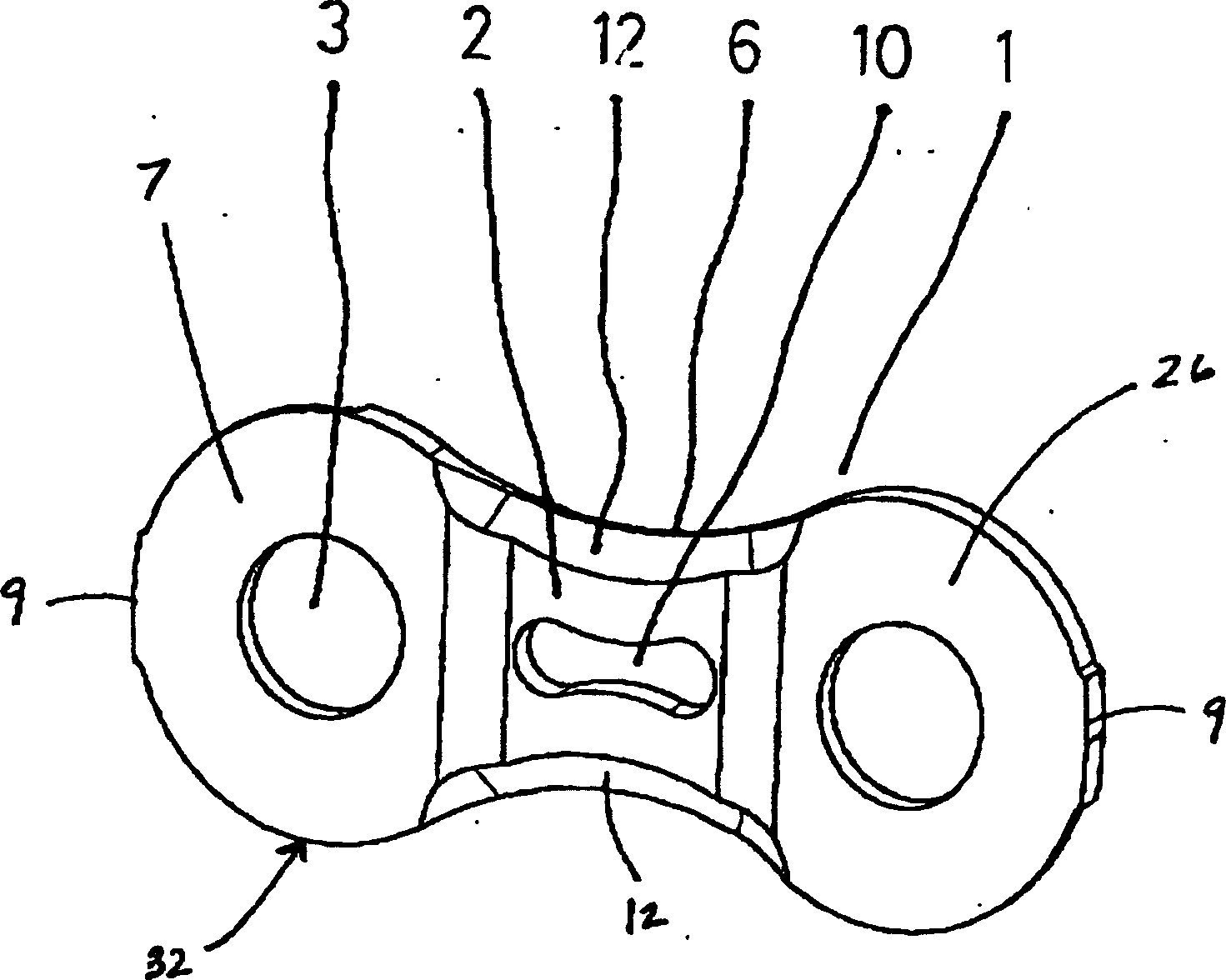
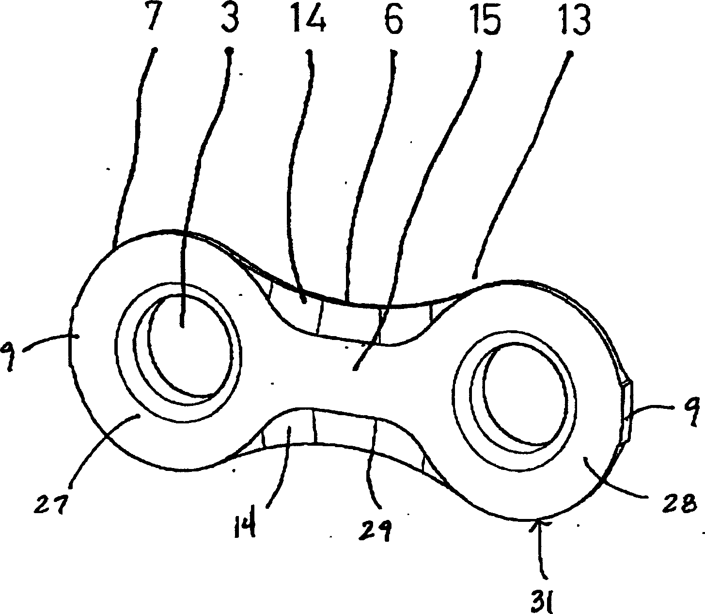
[0060] Figure 1-6 A bicycle drive chain 21 according to one embodiment of the present invention is shown. see Figure 5 and 6 , the bicycle drive chain 21 includes a plurality of outer link plates 1 and a plurality of inner link plates 13 . Pins 18 connect these inner and outer connecting plates 13, 1 to each other. Chain rollers 20 surround these pins 18 .

[0061] refer to figure 1 , the outer link plate 1 comprises first and second convex portions 7 , 26 and a concave portion 6 extending between the first and second convex portions 7 , 26 . The concave portion 6 has the projecting area 2 on the outer surface 33 of the outer link plate 1 . The first and second male parts 7 , 26 have holes 3 for receiving pins 18 . These holes 3 have rivet head pockets 4 for receiving rivet heads 19 of pins 18 . The protruding area 2 extends outwards as far as the rivet heads 19 or slightly beyond them, thereby preventing the rivet heads 19 from scratching on the sprocket 22 . The c...


PUM


Abstract

A bicycle drive chain for transferring drive force to at least one chain wheel. The chain includes a plurality of inner and outer chain links connected by pins. Chain rollers surround the pins. The inner and outer link plates have the same outer contour but have different profiles. The outer link plates have a protruding region extending from a concave section and the inner link plate includes deflection chamfers located on an outer surface. The outer link plate further includes chamfers diagonally opposed from each other located at first and second convex sections on an outer surface. The inner link plate has chamfers located on an inner surface that taper off near ends of the inner link plate.

Description

technical field [0001] The present invention relates to a bicycle drive chain, and more particularly to a bicycle drive chain including an outer link plate having a projecting region and an inner link plate having a chamfer on the outer surface. Background technique [0002] A bicycle drive chain for a derailleur-equipped bicycle includes inner and outer links pivotally connected to each other. The inner and outer links include spaces between the links for accommodating the teeth of the sprockets. The structure of these links is optimized to provide fast and reliable shifting operation. The operation of a chain shifting from a small sprocket to a large sprocket is fundamentally different from the operation of a chain shifting from a large sprocket to a small sprocket. During shifting operation from the small sprocket to the large sprocket, the first tooth of the large sprocket only engages between the outer pair of link plates. Conversely, during a shifting operation from...

Claims


Application Information

Patent Timeline
Patent Type & Authority Applications(China)
IPC IPC(8): F16G13/06
CPCF16G13/06
Inventor 马库斯·莱特佩德罗·米格尔·努涅斯·桑托斯若昂·皮雷斯
Owner SRAM
Why Eureka
Try Eureka