
Three-dimensional conveyer

A conveyor, three-dimensional technology, applied in the direction of conveyors, conveyor objects, transportation and packaging, etc., can solve the problems of conveyor chain bending, large area of ​​conveyor chain, unsuitable sprockets, etc.

Inactive Publication Date: 2005-09-14
前田弘
View PDF1 Cites 6 Cited by
  • Summary
  • Abstract
  • Description
  • Claims
  • Application Information

AI Technical Summary

Problems solved by technology

[0006] Therefore, a conveyor chain line with a large top plate for conveying large items cannot be bent at a small radius of curvature, and installing such a conveyor chain requires a large area, which is also inconvenient
[0007] In addition, on the return journey of the cycle, the top plate of the above-mentioned known conveyor is necessarily inverted, since the conveying surface is twisted up and down, so that the conveyor can only be used in one direction, and the return stroke cannot be used for conveying items
[0008] Moreover, any conventional conveyor using a chain can only be driven by a special sprocket with a structure specially designed for that chain only: the general sprockets for roller chains conforming to JIS or ISO standards are in this is not applicable

Method used


Image

  • Three-dimensional conveyer
  • Three-dimensional conveyer
  • Three-dimensional conveyer

Examples


Embodiment Construction

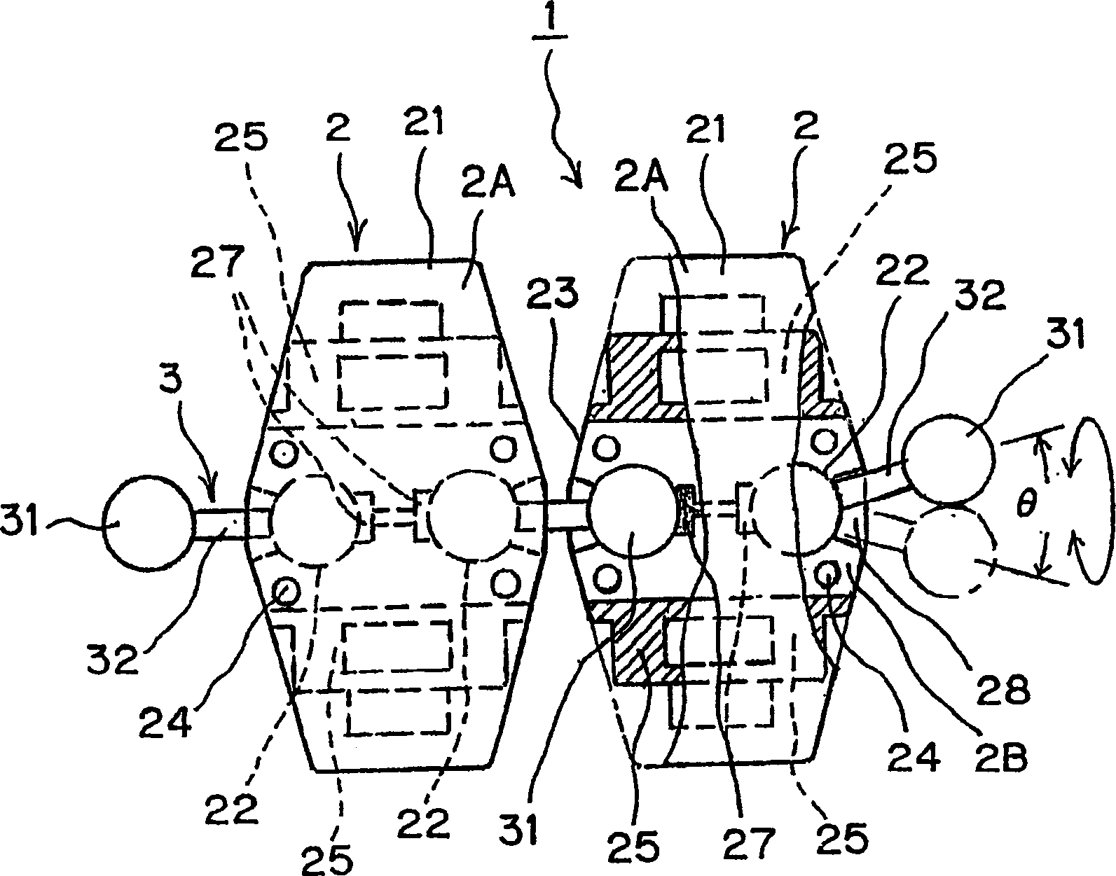
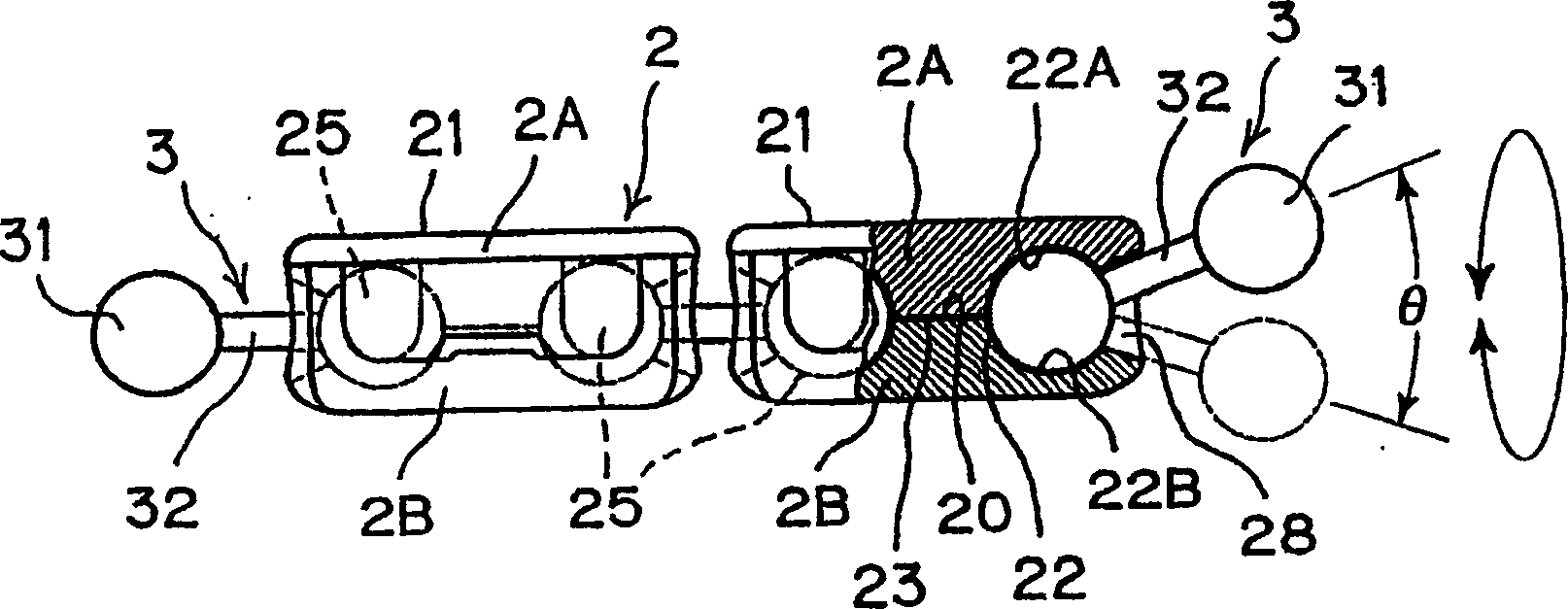
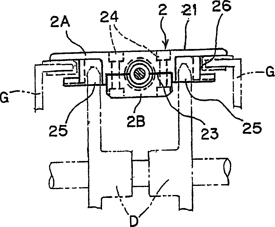
[0058] The following by reference Figure 1-14 The present invention is explained in detail.

[0059] The number 1 indicates the teleporter. The conveyor 1 is composed of several top trays 2 and connectors 3 for sequentially connecting adjacent top tray units. Each top tray unit 2 is made up of a top tray 2A having a top tray surface 21 for retaining items to be conveyed thereon and a tray bottom surface 23, and a buckle tray 2B having a tray bottom surface fitted to the top tray 2A The upper buckle surface 20.

[0060] On the top plate unit 2, two ball-holding cavities 22 are respectively formed in a nearly hemispherical shape, parallel to the traveling direction of the top plate unit.

[0061] By combining the nearly hemispherical concave surface 22A formed on the bottom surface 23 of the top plate 2A with the nearly hemispherical concave surface 22B formed on the buckle surface 20 of the buckle plate 2B, the ball-holding cavity 22 is formed in a nearly spherical shape. ...


PUM


Abstract

A three-dimensional conveyor is provided which can be curved in a small curvature even with a wide top plate unit for forming a conveyance face and can be moved in three-dimensional directions, vertically, laterally, or slantingly, and which is turnable around the conveyance direction axis. The three-dimensional conveyor has top plate units connected by couplers. The respective top plate unit has two ball-holding cavities at the front portion and the rear portion thereof for holding terminal balls of the coupler, as the joints. The terminal balls are fit loosely into the ball-holding cavities non-detachably, so that the top plate units can be slanted freely within a prescribed angle range. Further, the top plate units have respectively an engaging portion on each side of the ball-holding cavity on the bottom face of the top plate units to engage with a standardized sprocket to be driven by the rotating driving force the sprocket in a desired direction, vertically or horizontally.

Description

technical field [0001] The present invention relates to a three-dimensional conveyor capable of effectively arranging transmission lines in a two-dimensional or three-dimensional direction with a high degree of freedom of arrangement in a small space. The direction of the conveying line for containers and the like or the like is to make a U-turn with a small curvature or go up or down on multiple circulation steps in a small space. Background technique [0002] A variety of conveyors for conveying items in three dimensions have been disclosed. For example, Japanese Patent Application Laid-Open No. 2001-139121 discloses a chain structure for a three-dimensional conveyor line. Japanese patent Kohyo 2001-517591 (published by Japanese translation of PCT application) discloses a chain conveyor system. [0003] The chain structure disclosed in the above-mentioned Japanese Patent Application Laid-Open No. 2001-139121 is composed of a top tray for transporting articles thereon and...

Claims


Application Information

Patent Timeline
Patent Type & Authority Applications(China)
IPC IPC(8): B65G17/08B65G17/40B65G17/48B65G47/38
CPCB65G17/48B65G2201/02B65G17/40B65G47/38B65G17/086
Inventor 前田弘
Owner 前田弘
Learn More