Signal processing apparatus, method and program
一种信号处理、信号的技术,应用在图像通信、阴极射线管指示器、标准转换等方向,能够解决规模大等问题
- Summary
- Abstract
- Description
- Claims
- Application Information
AI Technical Summary
Problems solved by technology
Method used
Image

Examples
no. 1 example
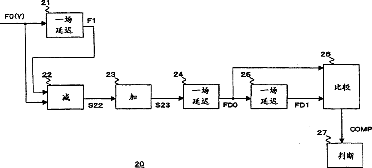
[0049] FIG. 1 is a functional block diagram of a signal processing device 20 of this embodiment.
[0050] As shown in FIG. 1 , the signal processing device 20 has, for example, a one-field delay circuit 21 , a subtracter circuit 22 , an adder circuit 23 , one-field delay circuits 24 and 25 , a comparison circuit 26 and a judgment circuit 27 .
[0051] Here, one field delay circuit 21 corresponds to the first delay device of the present invention, the subtractor circuit 22 and the adder circuit 23 correspond to the processing device of the present invention, and one field delay circuit 25 corresponds to the second delay device of the present invention, And the subtracter circuit 22 and the judging circuit 27 correspond to judging means or detecting means of the present invention.
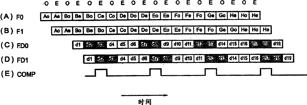
[0052] 2A-2E are views illustrating the signal shown in FIG. 1. In this case, the luminance signal F0(Y) of the film video signal (described earlier with FIG. 11) of the 3-2 pull-down conversion is t...
no. 2 example
[0095] Next, a case where the signal processing apparatus 20 of the first embodiment is used in a DVD (Digital Versatile Disc) player will be described.
[0096] FIG. 4 is a functional block diagram of the DVD player 30 of this embodiment.
[0097] As shown in Fig. 4, DVD player 30 has for example DVD drive 1, MPEG (Motion Picture Experts Group) decoder 2, one-field delay circuit 3, selector circuit 4, time axis compression circuit 5, time axis compression circuit 6, Selector circuit 7 , D / A conversion circuit 8 , controller 9 , one-field delay circuit 21 , subtractor circuit 22 , adder circuit 23 , one-field delay circuit 24 , one-field delay circuit 25 and comparison circuit 26 .
[0098] In Fig. 4, the labeling of one-field delay circuit 21, subtractor circuit 22, adder circuit 23, one-field delay circuit 24, one-field delay circuit 25 and comparison circuit 26 is also the same as that of the first embodiment in Fig. 1 same as described in .
[0099] The DVD drive 1 outpu...
no. 3 example
[0133] The above series of processing can be executed by hardware or by software. For example, in this case, a DVD player is configured by a personal computer as shown in FIG. 10 .
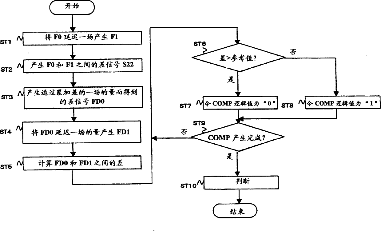
[0134] In FIG. 10 , a CPU (Central Processing Unit) 41 executes various processes according to programs stored in a ROM (Read Only Memory) or loaded from a storage unit 48 into a RAM (Random Access Memory) 43 . This program corresponds to the program of the present invention, and describes various routines including, for example, the routine shown in FIG. 3 .
[0135] The RAM 43 also appropriately stores data required when various types of processing are executed by the CPU 41 .
[0136] The CPU 41 , ROM 42 and RAM 43 are connected to each other by a bus 44 . The bus 44 has an input / output interface 45 connected thereto.
[0137] The input / output interface 45 has an input section 46 equipped with a keyboard, a mouse, etc., a display such as a CRT, an LCD, etc., an output section equipped with a...
PUM
 Abstract
Description
Claims
Application Information
 - R&D
- Intellectual Property
- Life Sciences
- Materials
- Tech Scout
- Unparalleled Data Quality
- Higher Quality Content
- 60% Fewer Hallucinations
Browse by: Latest US Patents, China's latest patents, Technical Efficacy Thesaurus, Application Domain, Technology Topic, Popular Technical Reports.
© 2025 PatSnap. All rights reserved.Legal|Privacy policy|Modern Slavery Act Transparency Statement|Sitemap|About US| Contact US: help@patsnap.com