Moving picture coding apparatus

A moving image and coding device technology, applied in image communication, television, electrical components, etc., can solve the problems of not disclosing the amount of calculation and maintaining high-resolution reference images, and achieve the effect of reducing the amount of calculation

Inactive Publication Date: 2005-09-21
PANASONIC CORP
View PDF4 Cites 41 Cited by
  • Summary
  • Abstract
  • Description
  • Claims
  • Application Information

AI Technical Summary

Problems solved by technology

[0036] However, neither Patent Document 1 nor Patent Document 2 discloses reducing the amount of calculation required to generate a reference image using a 6-tap filter when performing sub-pixel-accurate motion prediction
In addition, the method disclosed in Patent Document 3 reduces the amount of redundant calculations by using a 6-tap filter for generating sub-pixels, but actually needs to calculate a range that is not used for searching when performing sub-pixel-accurate motion prediction, so that The image generating unit 2401 generates an overall interpolated image for an image
Another disadvantage of the method of Patent Document 3 is that it requires a high-capacity high-resolution reference image memory as a new component for holding the high-resolution reference image that has been interpolated through a 6-tap filter

Method used


Image

  • Moving picture coding apparatus
  • Moving picture coding apparatus
  • Moving picture coding apparatus

Examples


no. 1 example

[0074] A moving picture coding apparatus in a first embodiment of the present invention will be described. The moving picture encoding device of the present invention is a device which receives a moving picture signal as an input signal; encodes the picture; and outputs encoded information. It has wide applicability in combination with video storage devices or video delivery devices.

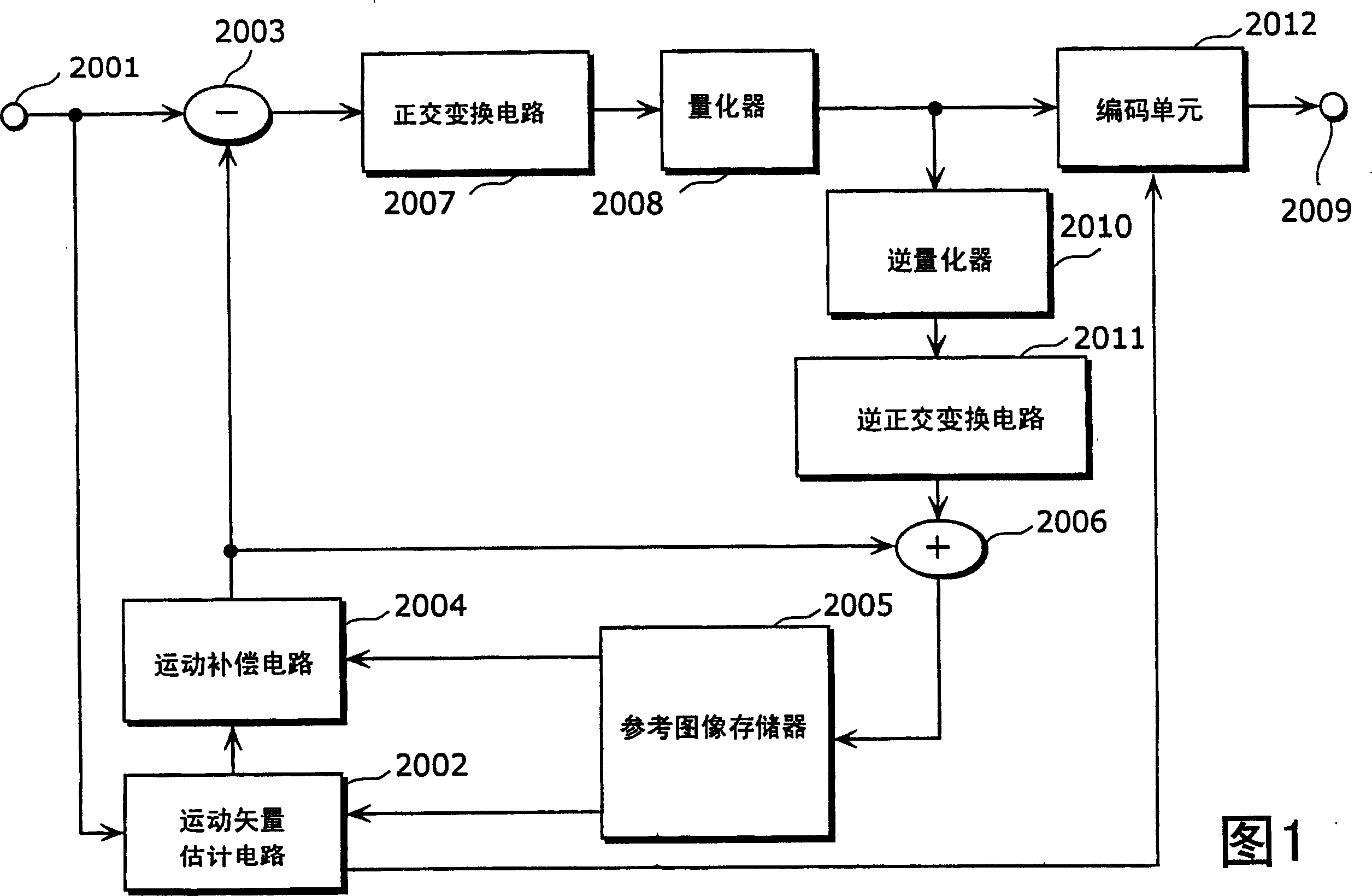
[0075] Fig. 7 is a block diagram showing the structure of the moving picture coding apparatus according to the first embodiment of the present invention. The same reference numerals are assigned to constituent elements performing the same operations as those of the conventional moving image encoding device shown in FIG. 1 . The motion picture coding apparatus in this embodiment limits the search of the motion vector to the search area generated in advance by the 2-tap filter, and for these motion vector candidates obtained as the search results, finally interpolated using the 6-tap filter Moti...

no. 2 example

[0147] If the programs for realizing the moving picture coding method and the moving picture decoding method shown in the above first embodiment are recorded on a recording medium such as a floppy disk, the above first embodiment can be easily executed in an independent computer system processing shown in .

[0148] 17A, 17B and 17C are diagrams showing a situation in which the moving picture coding method and the moving picture decoding method in the first embodiment described above are executed in a computer system using a computer program recorded on a storage medium such as a floppy disk.

[0149] FIG. 17B is a front view showing the appearance of a floppy disk, a cross-sectional view thereof, and the floppy disk itself, and FIG. 17A shows an example of the physical format of a floppy disk as a storage medium main body. The floppy disk FD is contained in the casing F, and a plurality of tracks Tr are provided annularly from the outer circumference to the inside in the radi...

no. 3 example

[0153] Furthermore, applications of the moving image coding method and moving image decoding method as shown in the first embodiment described above and a system using these methods will be described.

[0154] FIG. 18 is a block diagram showing the overall configuration of a content providing system ex100 for realizing content distribution services. The area for providing communication services is divided into cells of desired size, and base stations ex107 to ex110, which are fixed radio base stations, are provided in each cell.

[0155] In this content providing system ex100, devices such as a computer ex111, a personal digital assistant (PDA) ex112, a mobile phone ex114, and a camera-equipped mobile phone ex115 are connected via an Internet service provider ex102, a telephone network ex104, and base stations ex107 to ex110 to the Internet.

[0156] However, the content providing system ex100 is not limited to the configuration shown in FIG. 18, and any combination of them c...


PUM


Abstract

A motion vector estimation circuit ( 101 ) interpolates, with sub-pixel precision, a prediction block indicated by a motion vector estimated with integer-pixel precision as well as a region around the prediction block within a search area in a reference picture, using a 2 -tap pixel interpolator ( 605 ), and estimates two or more motion vectors indicating positions of prediction blocks having high correlation with a current block to be coded, within the interpolated region. A motion compensation circuit ( 102 ) interpolates, with sub-pixel precision, each of the prediction blocks indicated by the estimated motion vectors, using a 6 -tap pixel interpolator ( 901 ), compares the coding costs of the interpolated prediction blocks, and determines a motion vector indicating a position of a prediction block having highest correlation with the current block, from among the estimated motion vectors. As mentioned above, the number of motion vector candidates is narrowed down by sub-pixel precision motion prediction using a reference image created by a 2 -tap filter, and then motion compensation is performed on these motion vector candidates using a 6 -tap filter. Therefore, it becomes possible to achieve moving picture compression performance as high as sub-pixel precision motion prediction using a reference image created by a 6 -tap filter.

Description

technical field [0001] The present invention relates to a moving picture encoding device, and in particular, to an efficient motion estimation allowing sub-pixel accuracy in a large scale integration system (LSI), software, etc. for encoding moving pictures with limited resources motion picture encoding device. Background technique [0002] In recent years, with the improvement of computer performance and the increase of Internet communication capabilities, digital contents have been widely used. Digital DVD has rapidly replaced the analog video home system (VHS) for the recording of moving pictures (video) as a sequence of still pictures. A video sequence contains a huge amount of information, and thus techniques to compress the size of the video are necessary to process the video information into digital data. In digital video content, encoding is used to compress information. This video compression technique has been used in various products. For example, MPGE-2 is us...

Claims


Application Information

Patent Timeline
Patent Type & Authority Applications(China)
IPC IPC(8): H04N7/26H04N7/36H04N7/46H04N7/50
CPCH04N7/364H04N19/00781H04N19/00278H04N19/00187H04N19/00721H04N19/00606H04N19/0063H04N19/0069H04N19/00733H04N19/00739H04N19/00024H04N19/0089H04N19/105H04N19/15H04N19/176H04N19/51H04N19/517H04N19/523H04N19/533H04N19/577H04N19/61H04N19/80
Inventor 小宫大作柴原阳司角野真也
Owner PANASONIC CORP
Why Eureka
Try Eureka