Construction for attaching net member to chair seat or backrest frame

A frame and component technology, which is applied in the structural field of installing grid components on a frame for a seat or a backrest of a seat, can solve problems such as inability to provide elasticity and the like

Inactive Publication Date: 2005-09-21
OKAMURA MFG CO LTD
View PDF3 Cites 15 Cited by
  • Summary
  • Abstract
  • Description
  • Claims
  • Application Information

AI Technical Summary

Problems solved by technology

Thus the seat and backrest cannot provide enough flexibility

Method used


Image

  • Construction for attaching net member to chair seat or backrest frame
  • Construction for attaching net member to chair seat or backrest frame
  • Construction for attaching net member to chair seat or backrest frame

Examples


Embodiment Construction

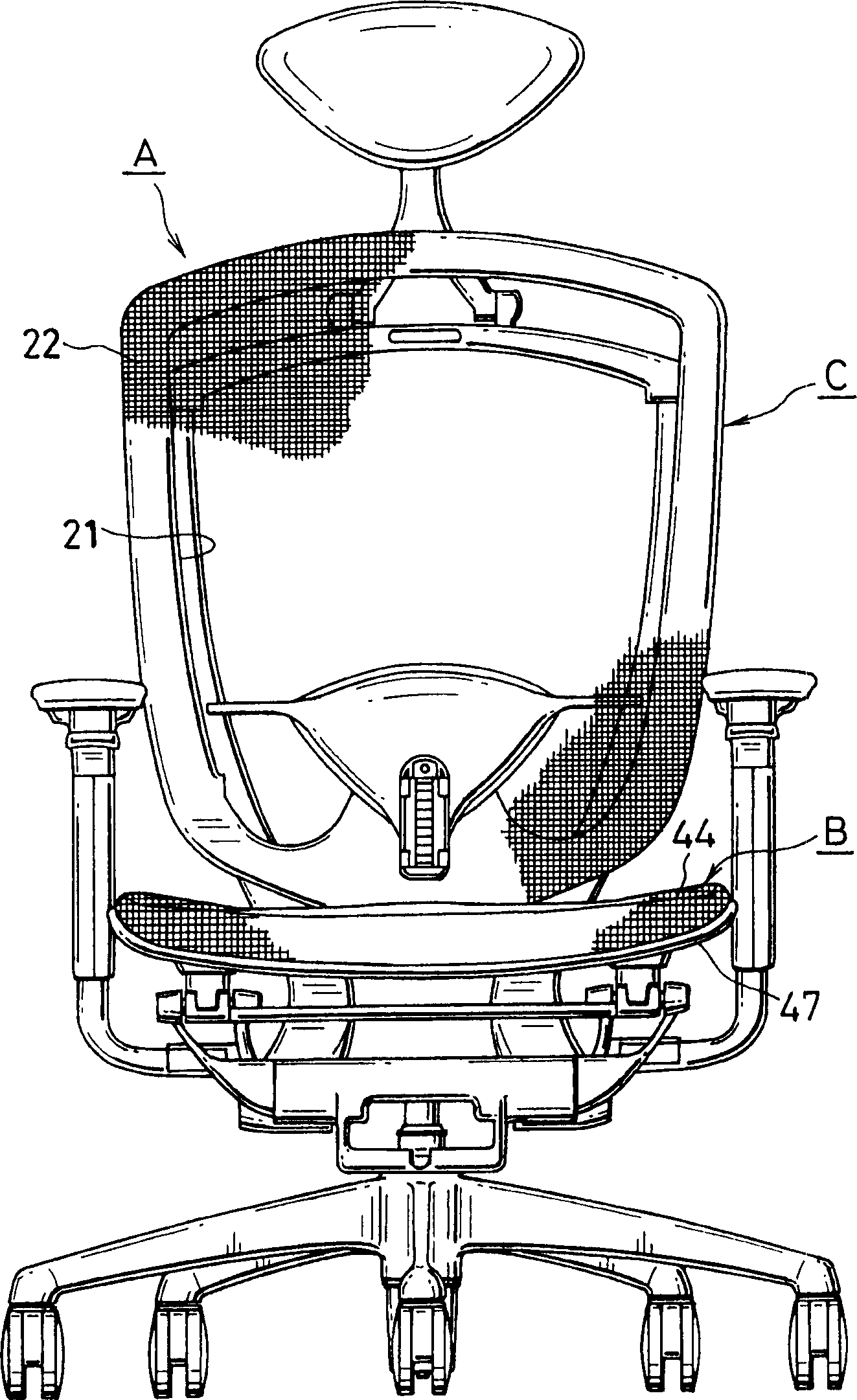
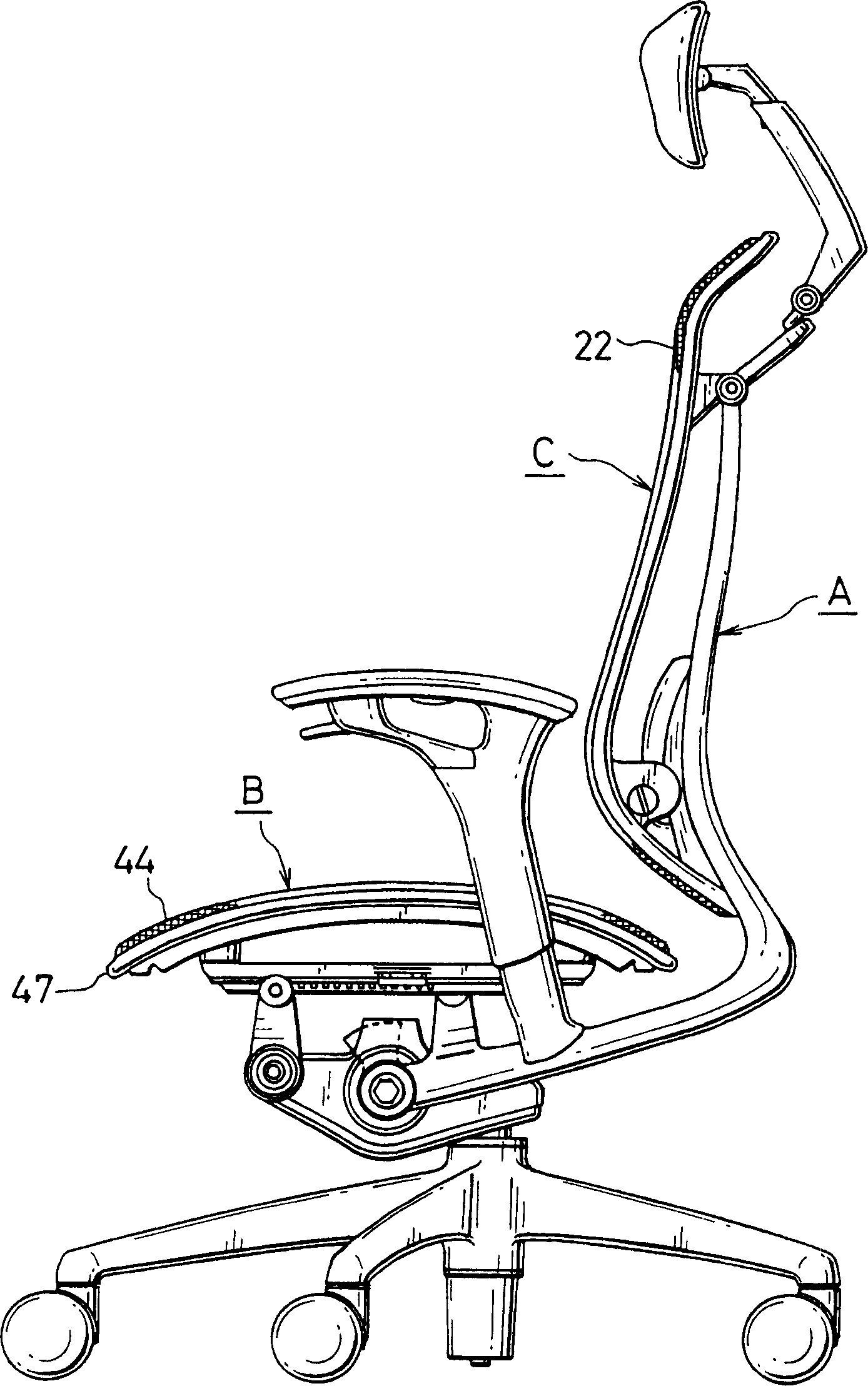
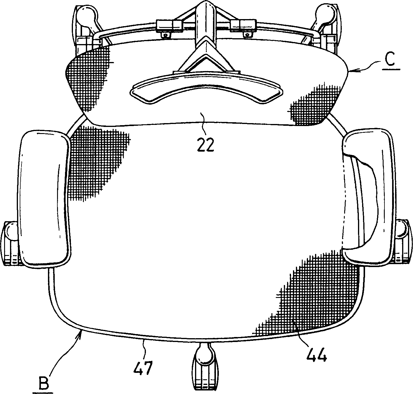
[0044] figure 1 is a front view of Seat "A" with a structure in which mesh parts are mounted to the seat or back frame, figure 2 is its right view, image 3 is its top view.

[0045] Next, a first embodiment of the present invention will be described. The present invention is not only applicable to figure 2 The seat portion "B" of the seat "A" can also be applied to the backrest "C" of the seat "A".

[0046] Such as Figure 4 with 5 As shown, in seat "B", the perimeter of a grid member 2, such as high tensile plastic, is placed over the perimeter of the closed loop seat frame 1 and folded over. A joint frame 3 similar in shape to the seat frame 1 is placed on the lower surface of the folded portion 2 a and connected by screws 4 .

[0047] A plurality of threaded holes 5 and through holes 6 are respectively formed on the coupling frame 3 on the lower surface of the seat frame 1, and the positions of the threaded holes and the through holes correspond to each other.

...


PUM


Abstract

A net member is stretched over a frame for a seat and backrest of a chair. An engagement member attached to the end of the net member is inserted into an engagement groove on the lower surface of the basic frame. A binding frame is pressed onto the lower surface of the basic frame and the net member is fixed between the basic frame and the binding frame by the engagement piece. Warps are woven or knitted in a mesh structure over the seat and backrest to wefts comprising elastic yarns and chenille yarns.

Description

technical field [0001] The present invention relates to a structure for mounting a mesh member to a frame of a seat or a backrest of a seat, a method for mounting the mesh member to the frame, and a seat having a netting in which warp and weft are Woven or knitted together. Background technique [0002] In the traditional seat structure of a seat, a high-tension elastic mesh member including perforated plates is spread on a closed-loop seat frame, and the outer periphery of the mesh member is placed on the upper outer surface of the seat frame and folded to the seat frame. the lower surface of the frame. Fix the folded part to the seat frame with screws. Such structures are disclosed in Japanese Patent Laid-Open Nos. 11-244103 and 2002-165672. [0003] However, mounting the outer perimeter of the mesh member on the seat frame under non-uniform tension is not a straightforward process. This process is extremely laborious due to non-uniform tension. Wrinkles and slack app...

Claims


Application Information

Patent Timeline
Patent Type & Authority Applications(China)
IPC IPC(8): A47C7/22A47C7/28A47C23/26A47C31/02
CPCA47C7/282A47C31/023A47C7/40A47C31/04A47C7/02A47C31/02
Inventor 沼直树成田哲也五十岚僚
Owner OKAMURA MFG CO LTD
Why Eureka
Try Eureka