Transmission controller for continuously variable transmission system

A continuously variable transmission, control device technology, applied in the direction of transmission, transmission control, components with teeth, etc., can solve the problem of increased weight and assembly man-hours, complex structure, and inability to return the speed ratio of the continuously variable transmission to the low ratio side and other problems to achieve the effect of preventing driving force loss and improving performance

Inactive Publication Date: 2006-04-05
HONDA MOTOR CO LTD
View PDF1 Cites 12 Cited by
  • Summary
  • Abstract
  • Description
  • Claims
  • Application Information

AI Technical Summary

Problems solved by technology

[0006] However, the technology of the above-mentioned Patent Document 1 has a problem that the gear ratio of the continuously variable transmission cannot be returned to the low ratio side when the crankshaft of the engine is less than a predetermined rotational speed an

Method used


Image

  • Transmission controller for continuously variable transmission system
  • Transmission controller for continuously variable transmission system
  • Transmission controller for continuously variable transmission system

Examples


Embodiment Construction

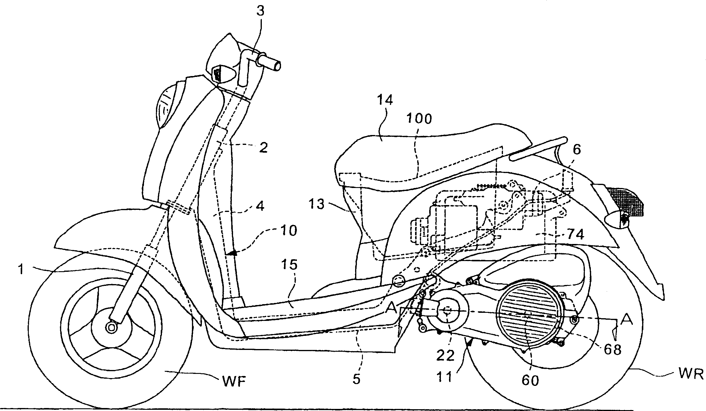
[0026] Hereinafter, preferred embodiments of the present invention will be described in detail with reference to the drawings. figure 1 It is a side view showing one embodiment of a compact hybrid vehicle to which the present invention is applied.

[0027] A hybrid vehicle has a front fork 1 pivotally supporting a front wheel WF at the front of the vehicle body, the front fork 1 is pivotally supported on a head pipe 2 , and the hybrid vehicle can be steered by operating a handle 3 . A down tube 4 is attached rearward and downward from the head tube 2 , and an intermediate frame 5 extends substantially horizontally from the lower end of the down tube 4 . In addition, a rear frame 6 is formed rearward and upward from the rear end of the middle frame 5 .

[0028] One end of a power unit 11 including an engine as a power source and a drive motor is pivotally attached to the vehicle frame 10 configured in this way. The power unit 11 is provided with a rotatable drive wheel, that ...


PUM


Abstract

The invention provides a variable speed control device of a variable speed case, which leads the variation ratio to stably return to a low ratio side even after a belt pulley at a driving side stops when in emergency deceleration, and has good production efficiency. The variable speed control device comprises a control unit. A vehicle speed sensor detects the emergency deceleration of a vehicle body (in step S2); after a belt pulley revolution transmitter detects that the belt pulley at the driving side stops (in step S4), when a variation ratio sensor detects that the variation ratio of the variable speed case does not return to the low ratio side which can obtain fully accelerating when restarting (in step S7), and then the control unit drives an actuator, so as to lead a moveable belt pulley half body at the driving side to move to the position of the low ratio side (in step S7). In addition, when the control unit detects a restarting intention of a hitching people according to a detecting signal from an air damper opening degree sensor (in step S12), the moveable belt pulley half body at the driving side is pressed towards a V-shaped transmission belt by the actuator (in step S13), and thus the slippage between the moveable belt pulley half body at the driving side and the V-shaped transmission belt is avoided, and the transmission loss of driving force is decreased when restarting.

Description

technical field [0001] The present invention relates to a speed change control device for a continuously variable transmission, and more particularly to a speed change control device for a continuously variable transmission capable of stably returning the speed change ratio to the low ratio side even after the drive side pulley stops rotating during sudden deceleration. Background technique [0002] As a conventional transmission mechanism that transmits the driving force of the engine to the driving wheels through the belt type continuously variable transmission, a centrifugal starting clutch is provided on the output side (driven side). According to this transmission mechanism, the torque transmission between the driving wheels and the continuously variable transmission can be disconnected when the vehicle is stopped in an emergency, so that the transmission ratio of the continuously variable transmission can be shifted to the low transmission ratio side (low ratio side) by...

Claims


Application Information

Patent Timeline
IPC IPC(8): F16H59/36F16H9/12
CPCF16H61/66259F16H2061/6605F16H61/04F16H61/66
Inventor 塚田善昭小岛浩孝大关孝内笹井弘明
Owner HONDA MOTOR CO LTD
Why Eureka
Try Eureka