Electrochromic color display having different electrochromic materials

An electrochromic material and electrochromic technology, applied in static indicators, instruments, nonlinear optics, etc., can solve problems such as inability to display multi-color images

Inactive Publication Date: 2005-09-21
KONINKLIJKE PHILIPS ELECTRONICS NV
View PDF1 Cites 38 Cited by
  • Summary
  • Abstract
  • Description
  • Claims
  • Application Information

AI Technical Summary

Problems solved by technology

Known electrochromic display devices cannot display multicolor images

Method used


Image

  • Electrochromic color display having different electrochromic materials
  • Electrochromic color display having different electrochromic materials
  • Electrochromic color display having different electrochromic materials

Examples


Embodiment Construction

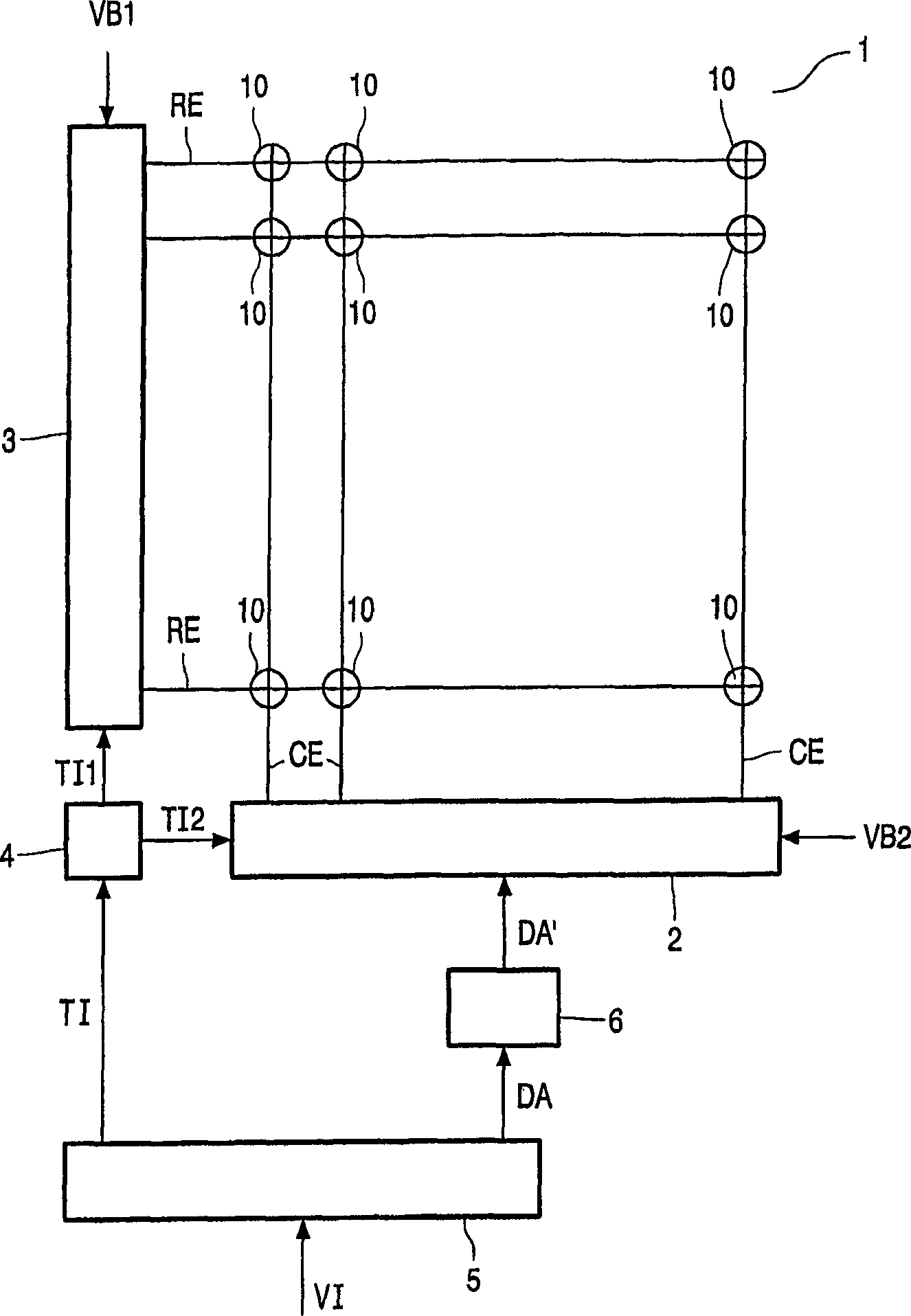
[0029] figure 1 A block diagram showing the electrochromic display and the driving circuit. The electrochromic display 1 comprises a matrix of electrochromic pixels 10 (also called pixels) associated with the intersections of row (or selection) electrodes RE extending in the row direction and column (or data) electrodes CE extending in the column direction. The row driver 3 supplies a selection voltage to the row electrode RE, and the column driver 2 supplies a data voltage to the column electrode CE. The data processor 5 receives the input video VI, provides the timing information TI to the controller 4 , and provides the data signal DA to the comparator 6 . The timing information TI may represent fields and lines in the video signal VI. Comparator 6 supplies data signal DA′ to column driver 2 . Comparator 6 is optional, if comparator 6 is omitted, data signal DA' is equal to DA. The controller 4 supplies the first control signal TI1 to the row driver 3 and supplies the s...


PUM


Abstract

An electrochromic display comprises electrochrome pixels (10) which comprise at least a first electrochrome material (EL1) and a second electrochrome material (EL2) between two electrodes (E1, E2). Each of the electrochrome materials (EL1, EL2) has two stable states, in one state at a first voltage across the electrochrome pixel (10) the material is transparent, in the other state at a second voltage across the electrochrome pixel (10) the material absorbs a color and thus is colored. The material changes from the one state to the other state by applying the appropriate one of the first or the second voltage. The amount of change of the absorption of the color depends on the time the appropriate voltage is applied. The first electrochrome material (EL1) changes from a transparent state to a color absorbing state for at least partly absorbing a first color when a pixel voltage (VP) across the electrochrome pixel has the first value (V1). The first electrochrome material (EL1) changes from the color absorbing state to the transparent state when the pixel voltage (VP) has a second value (V2) which has a polarity opposite to the first value (V1). The second electrochrome material (EL2) changes from a transparent state to a color absorbing state for at least partly absorbing a second color different than the first color when the pixel voltage (VP) has a third value (V3) which has an absolute value smaller than an absolute value of the first value (V1). The second electro-chrome material (EL2) changes from the color absorbing state to the transparent state when the pixel voltage (VP) has a fourth value (V4) which has a polarity opposite to the third value (V3). An absolute value of the fourth value (V4) is smaller than an absolute value of the second value (V2).

Description

technical field [0001] The present invention relates to an electrochromic display, a driver circuit for driving an electrochromic pixel of an electrochromic display, a display device comprising an electrochromic display and a driver circuit, and an electrochromic display device for an electrochromic display. Driving method of color-changing pixels. Background technique [0002] US-A-4,304,465 discloses an electrochromic display device having a polymer film on the display electrodes. During the writing step, the polymer film on the display electrodes is oxidized to a colored opaque form. During the wiping step, the polymer film is reduced to a neutral transparent morphology. Known electrochromic display devices cannot display multicolor images. Contents of the invention [0003] The object of the present invention is to provide an electrochromic display device capable of producing multi-color images. [0004] A first aspect of the present invention is to provide an elec...

Claims


Application Information

Patent Timeline
Patent Type & Authority Applications(China)
IPC IPC(8): G02F1/153G02F1/15G02F1/163G09G3/20G09G3/38
CPCG02F1/163G02F1/15G09G2300/0842G09G3/2014G02F2203/34G02F2001/1512G09G3/38G02F2001/15145
Inventor M·T·约翰逊L·J·M·施兰根H·J·B·贾格特
Owner KONINKLIJKE PHILIPS ELECTRONICS NV
Why Eureka
Try Eureka