Symmetric beamline and methods for generating a mass-analyzed ribbon ion beam

A technology of mass analysis and mass analyzer, applied in the direction of ion beam tubes, discharge tubes, electrical components, etc., can solve the problems of beam expansion and difficulty in providing low-energy high-current beams, and achieve injection uniformity and transport loss Approximately homogeneous, prevents contamination and particles from reaching the effect

Inactive Publication Date: 2005-09-21
AXCELIS TECHNOLOGIES
View PDF0 Cites 8 Cited by
  • Summary
  • Abstract
  • Description
  • Claims
  • Application Information

AI Technical Summary

Problems solved by technology

However, such systems suffer from difficulties in providing high fluence beams at low energies due to their attendant high beam densities which tend to cause beam enlargement due to space charge

Method used


Image

  • Symmetric beamline and methods for generating a mass-analyzed ribbon ion beam
  • Symmetric beamline and methods for generating a mass-analyzed ribbon ion beam
  • Symmetric beamline and methods for generating a mass-analyzed ribbon ion beam

Examples


Embodiment Construction

[0028] The present invention will now be described with reference to the drawings, and the same reference numerals are used to denote the same elements in all the drawings. The present invention provides a method and system for providing a mass-analyzed ribbon beam for ion implantation of workpieces, such as semiconductor wafers. Hereinafter, an embodiment of the present invention is illustrated and described with reference to the accompanying drawings. The illustration and the following description are exemplary in nature and not restrictive. Therefore, it is understood that variations of the system and method shown, as well as other embodiments than those shown here, are deemed to fall within the scope of the present invention and the scope of the appended claims.

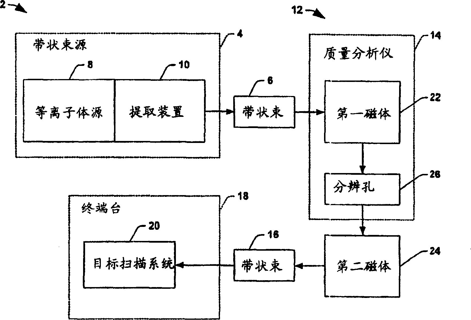
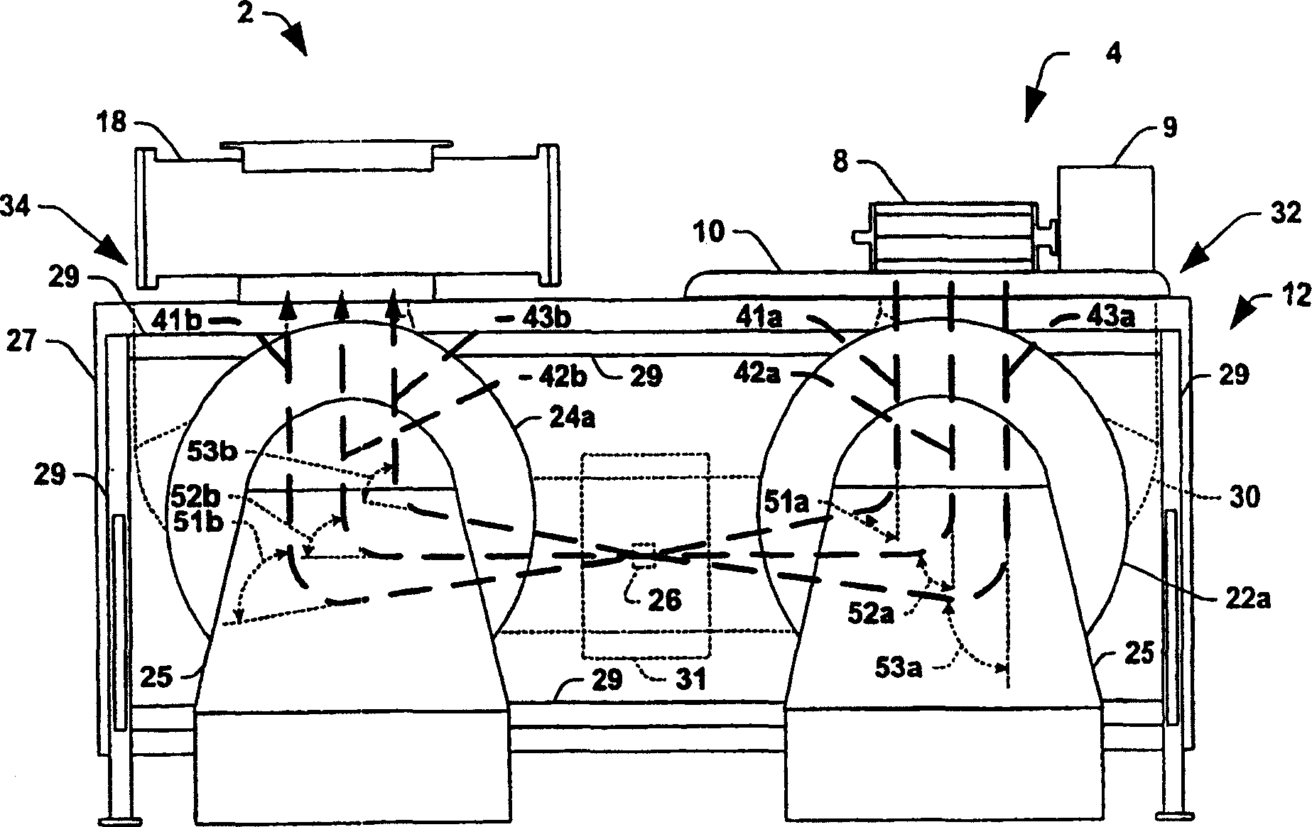
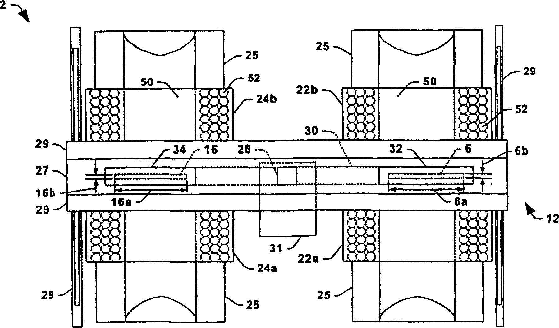
[0029] Start referencing figure 1 with 2a -2c, the present invention provides an ion implantation system 2 including an ion source 4 for generating an elongated (eg, ribbon) ion beam 6 along a longitudinal beam path...


PUM


Abstract

Ion implantation systems and beamlines therefor are disclosed, in which a ribbon beam of a relatively large aspect ratio is mass analyzed and collimated to provide a mass analyzed ribbon beam for use in implanting one or more workpieces. The beamline system (12) comprises two similar magnets (22, 24), where the first magnet (22) mass analyzes the ribbon beam to provide an intermediate mass analyzed ion beam, and the second magnet (24) collimates the intermediate beam to provide a uniform mass analyzed ribbon beam to an end station.(18). The symmetrical system provides equidistant beam trajectories (41, 43) for ions across the elongated beam width so as to mitigate non-linearities in the beam transport through the system, such that the resultant mass analyzed beam is highly uniform.

Description

Technical field [0001] The present invention generally relates to ion implantation systems, and more particularly to a symmetrical beamline system and method for generating a mass-analyzed ribbon ion beam in the ion implantation system. Background technique [0002] In integrated circuit manufacturing, ion implantation systems are used to dope semiconductors with impurities. In this system, the ion source ionizes desired impurity elements, which are extracted from the source in the form of an ion beam having the desired energy. The ion beam is then directed to the surface of the semiconductor wafer to implant impurity elements into the wafer. The ions in the beam penetrate the surface of the wafer to form regions of desired conductivity (such as in the process of manufacturing transistor devices in the wafer). The implantation process is usually carried out in a high-vacuum processing chamber, which prevents the ion beam from being scattered due to collisions with residual gas mo...

Claims


Application Information

Patent Timeline
Patent Type & Authority Applications(China)
IPC IPC(8): H01J27/16H01J27/00H01J27/06H01J37/04H01J37/05H01J37/08H01J37/317H01L21/265
CPCH01J37/05H01J2237/0835H01J37/08H01J37/3171H01J2237/31701
Inventor V·本维尼斯特
Owner AXCELIS TECHNOLOGIES
Why Eureka
Try Eureka