Broadband/multi-band circular array antenna

An array antenna and multi-band technology, which is applied in the direction of antenna, antenna array, and antenna array with separate power supply, can solve the problems of impractical and unapplicable antenna design

Active Publication Date: 2005-10-05
王氏电-光公司
View PDF1 Cites 21 Cited by
  • Summary
  • Abstract
  • Description
  • Claims
  • Application Information

AI Technical Summary

Problems solved by technology

Therefore, prior art antenna designs are not practical or even applicable for UHF (Ultra High Fr

Method used


Image

  • Broadband/multi-band circular array antenna
  • Broadband/multi-band circular array antenna
  • Broadband/multi-band circular array antenna

Examples


Embodiment Construction

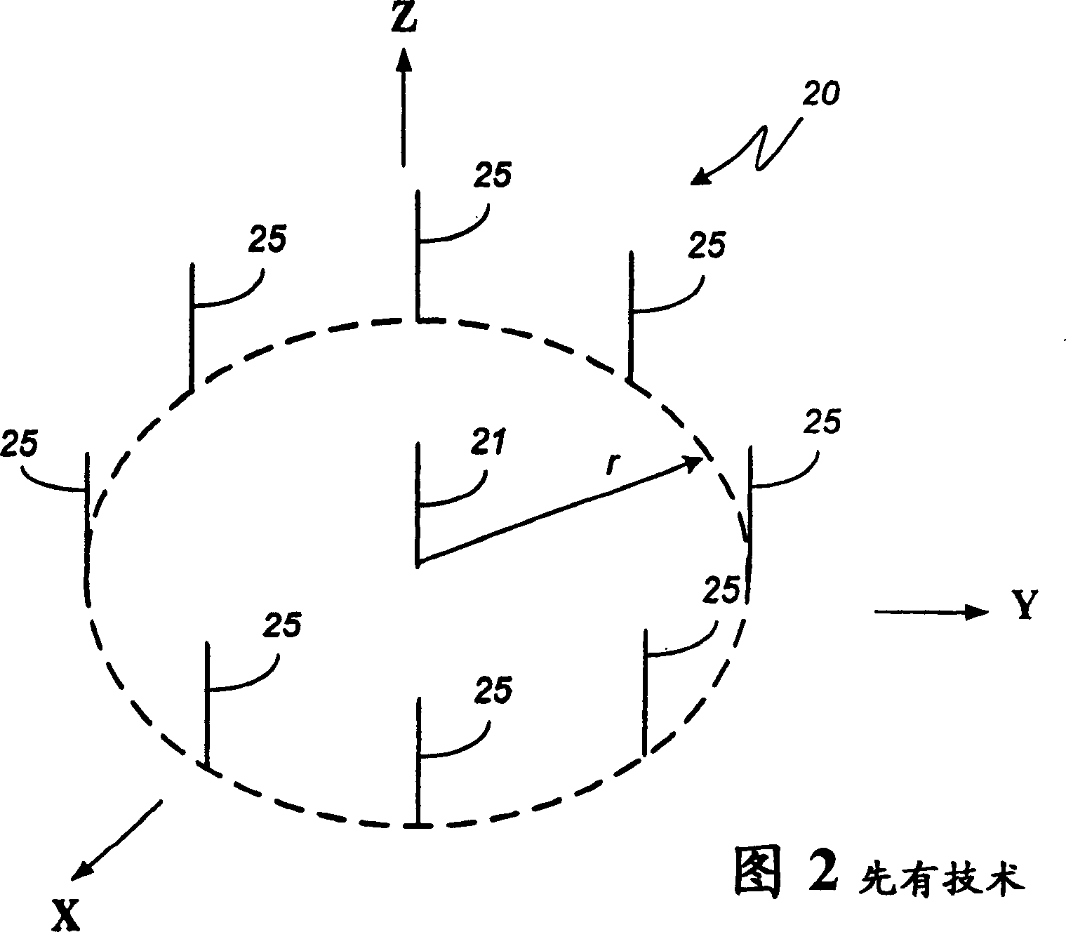
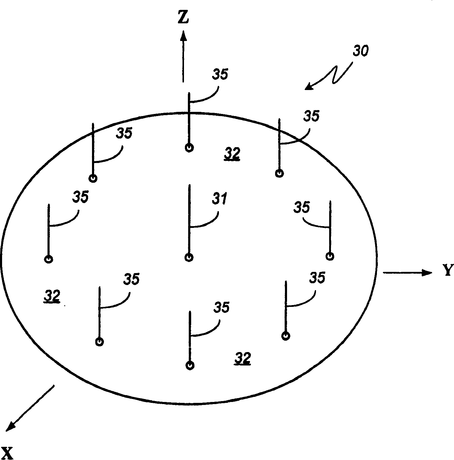
[0024] The broadband / multi-band circular array antenna of the present invention will be described in more detail below. One embodiment is a small, low profile broadband / multiband circular array antenna with electronically steered directional beams for omnidirectional coverage. The array includes a single excitation broadband / multi-band traveling wave antenna unit and a plurality of controlled surface waveguide units, and each surface waveguide unit is symmetrically arranged on a substantially circular centered on the excitation unit with respect to the excitation unit on the circumference of the shape and close to the excitation unit. The array elements are located on a ground plane, which is generally a reactive surface, but may also be a conductive surface. The single excitation unit is connected to the receiver and / or transmitter via a feed network. The excitation unit is a broadband / multi-band traveling-wave antenna with an omnidirectional radiation pattern. The unit is ...


PUM


Abstract

A broadband/multiband circular array antenna is disclosed. One embodiment comprises a circular directional array antenna comprising a driven omnidirectional traveling-wave antenna element coupled to a transceiver via a feed and a plurality of surface-waveguide elements symmetrically positioned about and spaced from the driven omnidirectional traveling-wave antenna element. Each surface-waveguide element receives a control signal configured to selectively alter its waveguide characteristics to electronically direct a beam to/from the array. The array provides a directionally controllable antenna beam with broadband/multiband frequency performance in a low profile design that is both economical and practical to produce and maintain.

Description

technical field [0001] This invention relates generally to radio frequency antennas and, more particularly, to circular array antennas with directional beams for omnidirectional coverage. Background technique [0002] Array antenna is a type of antenna that uses multi-element antennas to form fixed or controlled directional beams to perform important functions in wireless telecommunication, radar, navigation, guidance, electronic warfare, etc. Array antennas capable of both transmitting and receiving can be classified as: (1) phased array antennas, where each element is connected to a transmitter / receiver via a network to obtain the amplitude and phase distribution required for beamforming; (2) Unit switching array antenna, which realizes beamforming and beam control by turning on or off some units; (3) Yagi-Uda array antenna, in which most of the array units are parasitic coupled to one or a few excitation units. [0003] Existing array antennas are mainly of the first two...

Claims


Application Information

Patent Timeline
IPC IPC(8): H01Q3/00H01Q21/00H01Q21/06H01Q21/20
Inventor J·J·H·王
Owner 王氏电-光公司
Why Eureka
Try Eureka