Method of joining members, method of joining metallic members, radiation member, process for manufacturing the same, jig for the manufacturing and heat sink

A metal element and bonding jig technology, which is applied in the field of element bonding, metal element bonding, heat dissipation elements and their manufacture, jig for the manufacture of heat dissipation elements, and heat sinks, and can solve the problems of poor bonding, inability to bond, and fins 464. The base end portion 464a is fused and other problems, and the effect of high bonding strength and high deformation resistance is achieved.

Inactive Publication Date: 2005-10-05
NIPPON LIGHT METAL CO LTD
View PDF4 Cites 10 Cited by
  • Summary
  • Abstract
  • Description
  • Claims
  • Application Information

AI Technical Summary

Problems solved by technology

Therefore, the compressive stress from the bonding jig 463 cannot be sufficiently transmitted to the interface between the base plate 462 and the base end portion 464a of the fin 464, resulting in poor or impossible bonding.
Moreover, when the thickness of the base end portion 464a of the fin 464 is relatively thin (eg, less than 0.5 mm), there is a disadvantage that the base end portion 464a of the fin 464 is fused.
[0029] (2) Since the joining jig 463 is pressed into the side of the fin 464, the base end portion 464a in the composition of the fin 464 cannot be omitted, and the shape and structure of the heat dissipation element are thus limited.
[0030] (3) Since the joining jig 463 is pressed into the side of the fin 464, the base end 464a directly below the heat dissipation surface 464b and the substrate 462 remain unbonded, resulting in insufficient heat dissipation performance a

Method used


Image

  • Method of joining members, method of joining metallic members, radiation member, process for manufacturing the same, jig for the manufacturing and heat sink
  • Method of joining members, method of joining metallic members, radiation member, process for manufacturing the same, jig for the manufacturing and heat sink
  • Method of joining members, method of joining metallic members, radiation member, process for manufacturing the same, jig for the manufacturing and heat sink

Examples


Embodiment 1

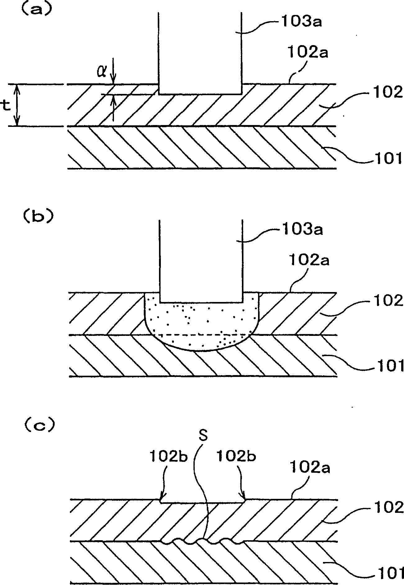
[0602] Set the width w of the flat surface of the circumferential surface of different joining jigs 1 (mm), groove width w 2 (mm), the ratio of the width of the flat part to the width of the groove w 1 / w 2 Finally, the experimental results of joint quality, appearance and mechanical load are shown in Table 5.

[0603] Plane

width w 1

(mm)

groove width

degree w 2

(mm)

w 1 / w 2

Groove dip

Angle θ

(°)

deep groove

degree(mm)

joint

quality

Exterior

mechanical load

charge

Example 1-1

1

1

1

0.5

1

Example 1-2

2

1

2

Example 1-3

3

1

3

Example 1-4

5

1

5

Example 1-5

2

3

0.67

...

Embodiment 2

[0612] After setting the inclination angle of the grooves on the circumferential surface of different bonding fixtures relative to the rotation direction and the number of grooves, the experimental results of the bonding quality, appearance, and mechanical load are shown in Table 6. On the other hand, only in the conditions of Comparative Example 2-2, the width of the joining jig was set to 10 mm.

[0613] groove inclination angle

θ (°)

groove inclination angle

θ(°)

groove depth

(mm)

Number of grooves

(strip)

join

quality

Exterior

machinery

the load

Example 2-1

0.5

2

1

8

Example 2-2

1

3

Example 2-3

2

2

Comparative example 2-1

3

1

×

×

Comparative example 2-2

0

0

×

[0...

Embodiment 3

[0623] After setting the depth of grooves on the circumferential surface of different bonding jigs, the experimental results of bonding quality, appearance, and mechanical load are shown in Table 7.

[0624] groove depth

(mm)

Plane

width w 1

(mm)

groove width

w 2 (mm)

groove slope

Angle θ(°)

Fixture pressing amount

(mm)

join

quality

Exterior

machinery

the load

Example 3-1

0.3

2

1

0.5

0.1~0.2

Example 3-2

0.4

Example 3-3

0.8

Example 3-4

1.2

Comparative example 3-1

0.2

×

×

Comparative example 3-2

2

0.3~0.5

Comparative example 3-3

no groove

×

×

[0625] ◎: Good / ×: Poor

[0626] ◎...


PUM

PropertyMeasurementUnit
Depthaaaaaaaaaa

Abstract

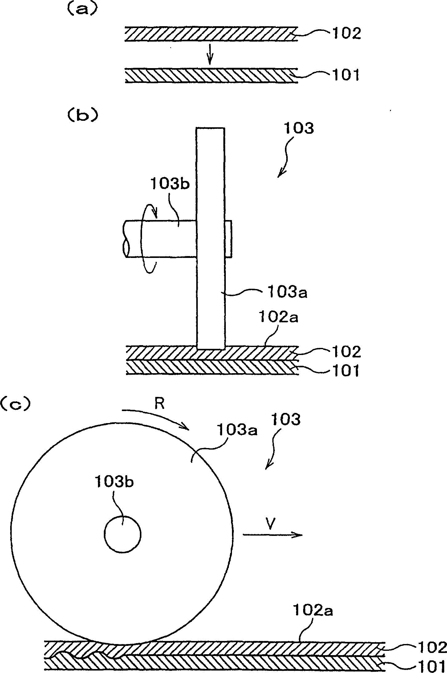
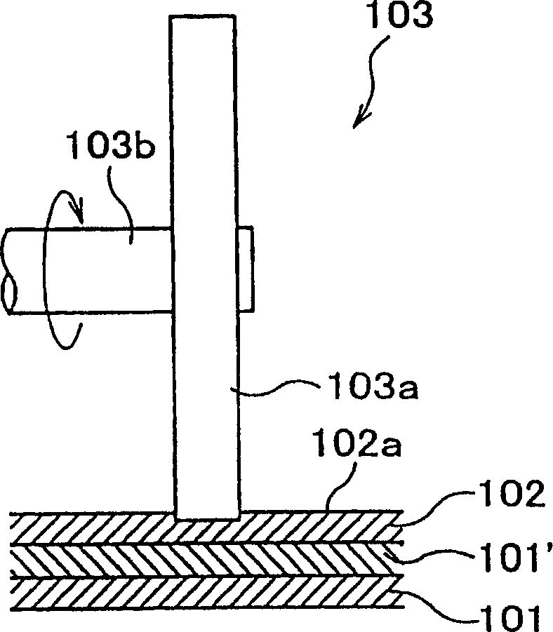
A method of joining two metallic members of different melting points piled on each other, which enables obtaining stable joined part quality and enables junction of large metallic members of complex configuration. Two or more metallic members (aluminum member (101) and copper member (102)) are joined to each other through a process comprising arranging two or more metallic members (aluminum member (101) and copper member (102)) so that these are piled on each other in the order of highness of melting point and moving the circumferential face of tool main body (103a) of disk-shaped junction tool (103) capable of rotating in the circumferential direction, while in the piling portion pressing the same in the surface (102a) of metallic member (copper member (102)) having the highest melting point among those of the metallic members, along the surface (102a) of metallic member (copper member (102)).

Description

technical field [0001] The first group of the present invention relates to a method of overlapping and joining metal elements having different melting points, and to a heat dissipation element having excellent bonding strength and a method of manufacturing a heat dissipation element having excellent bonding efficiency. [0002] The second group of the present invention relates to a method of superimposing and bonding a plurality of plate materials having a certain distance therebetween to one surface of a substrate, and also relates to the manufacture of cooling elements for ICs using the above bonding method. Heat radiating elements for peltier devices, radiating elements for motors, radiating elements for electronic control parts, etc., and manufacturing methods thereof, as well as jigs for manufacturing heat radiating elements used in the above-mentioned manufacturing methods. [0003] The third group of the present invention relates to heat sinks for cooling various electr...

Claims


Application Information

Patent Timeline
IPC IPC(8): B23K20/10
CPCB23K20/103
Inventor 堀久司堀田元司加濑泽善正齐藤久男南田刚牧田慎也江藤节樋野治道
Owner NIPPON LIGHT METAL CO LTD
Why Eureka
Try Eureka