Non-coherent fiber optic apparatus and imaging method

A technology of optical fiber devices and equipment, applied in the field of thods and apparatus for evalu, can solve the problems of imperfection, increase of manufacturing cost, and reduction of output of the device, etc.

Inactive Publication Date: 2005-10-05
G6 SCI CORP
View PDF15 Cites 2 Cited by
  • Summary
  • Abstract
  • Description
  • Claims
  • Application Information

AI Technical Summary

Problems solved by technology

[0004] The manufacturing process places certain constraints on the properties of the fibers that can be used in the device
Similarly, when...

Method used


Image

  • Non-coherent fiber optic apparatus and imaging method
  • Non-coherent fiber optic apparatus and imaging method
  • Non-coherent fiber optic apparatus and imaging method

Examples


Embodiment Construction

[0037] Although the present invention may be sensitive to embodiments in different forms, specific embodiments are shown in the drawings and detailed here, and it should be understood that the present disclosure should be regarded as an illustration of the principles of the present invention, rather than intended. The present invention is limited to what is illustrated and described herein.

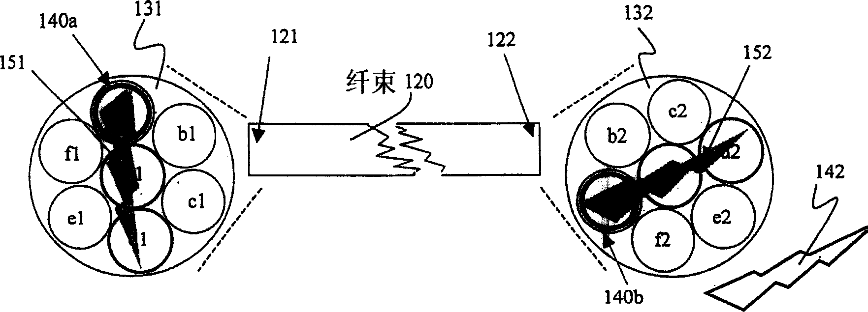
[0038] Figure 1 (prior art) illustrates a fiber bundle 120 having a first (reference) end 121 and a second end 122, which are further shown in enlarged views 131, 132, respectively. The fiber bundle shown has seven fibers designated a-g, which are further denoted a1-g1 at the first end, and the opposite ends of these fibers are denoted a2-g2 at the second end. Although there may be some axial rotation of the fiber bundle 120, see the enlarged view 131, at the first end 121, each fiber a1-g1 maintains its geometric position, that is, their side-by-side relationship, and at the second end 122 i...


PUM


Abstract

The present invention is a non-coherent optical fiber apparatus that may be used for imaging. Methods are described to produce geometric mapping data for an optical fiber apparatus. Images may be transmitted, reconstructed (using mapping data for the apparatus) and displayed. In addition, one or more fiber characteristics may be measured and used in conjunction with mapping data to further improve or correct the geometric, photometric or spectral content of images. The apparatus data described may be provided, by a manufacturer, for example, in raw form, or this data may be may be provided in a manner that is more user transparent, such as incorporating it into various image processing algorithms.

Description

Background technique [0001] In the field of optical fiber devices, rigid or flexible optical transmission fibers made of glass, plastic, polymer or fluid-filled tubes have many applications. The optical fiber can be further tailored to the application by selecting materials based on its mechanical properties, such as size, shape, and flexibility, and optical properties, such as refractive index and transmission characteristics. With proper design, optical fibers allow light to be transmitted over useful distances. Usually two or more optical fibers are formed into a bundle, forming a group, or otherwise placed in close association to form a fiber optic component bundle or conduit. Some applications of fiber optic devices include: delivering light to relatively inaccessible areas, such as dashboards and body cavities, guiding lasers used in medical procedures, and carrying communication data. In addition, in certain configurations, such as coherent beams, fiber optic devices can be...

Claims


Application Information

Patent Timeline
IPC IPC(8): G02B6/04G02B6/06
CPCG02B6/04G02B6/06
Inventor 加里·W·弗格森曾海山
Owner G6 SCI CORP
Why Eureka
Try Eureka