Optical scanning device

An optical scanning and light spot technology, applied in the field of scanning light spot power switch, can solve the problem of low edge intensity of radiation beam

Inactive Publication Date: 2005-10-12
KONINKLIJKE PHILIPS ELECTRONICS NV
View PDF6 Cites 4 Cited by
  • Summary
  • Abstract
  • Description
  • Claims
  • Application Information

AI Technical Summary

Problems solved by technology

In general, the result is that the rim intensity of the radiation beam entering the objective will then be rather low

Method used


Image

  • Optical scanning device
  • Optical scanning device
  • Optical scanning device

Examples


Embodiment Construction

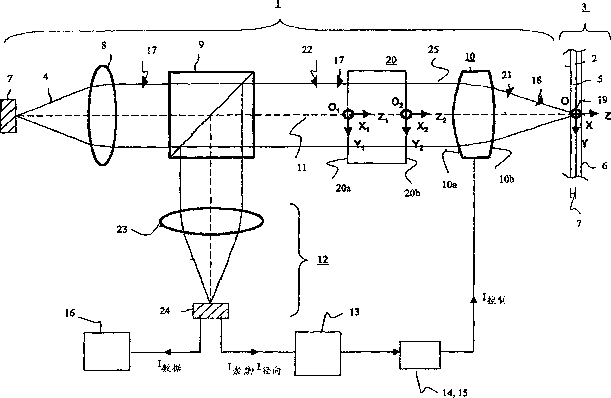
[0037] attached figure 1 is a schematic representation of the components of an optical scanning device according to the invention, which is designated by the reference number 1 . The optical scanning device 1 is capable of scanning at least one information layer 2 of at least one optical record carrier 3 by means of a radiation beam 4 in a first (writing) mode and in a second (reading) mode.

[0038] As shown, the optical record carrier 3 comprises a transparent layer 5 on one side of which an information layer 2 is arranged. The side of the information layer facing away from the transparent layer 5 is protected from environmental influences by the protective layer 6 . The transparent layer 5 acts as a substrate for the optical record carrier 3 by providing mechanical support for the information layer 2 . Alternatively, the transparent layer 5 may have the sole function of protecting the information layer 2, while the mechanical support is provided by a layer on the other si...


PUM


Abstract

A optical scanning device ( 1 ) for scanning an information layer ( 2 ) with a radiation beam ( 25 ) in a writing mode and a reading mode comprises a radiation source ( 7 ) for emitting the beam and an objective lens ( 10 ) for converging the beam so as to form a scanning spot ( 19 ) in the information layer. The device also includes a scanning spot power switch ( 20 ) for switching the size of the cross-section of the beam between a first size at the writing mode and a second, larger size at the reading mode so as to switch the rim intensity of the beam between a first intensity level (Irim,writing) at the writing mode and a second, higher intensity level (Irim,reading) at the reading mode, thereby switching the light power of the scanning spot between a first power level (Pwriting) at the writing mode and a second, lower power level (Preading) at the reading mode.

Description

technical field [0001] The invention relates to an optical scanning device for scanning an information layer by means of a radiation beam in a writing mode and in a reading mode, the device comprising: [0002] a radiation source for emitting said radiation beam, [0003] an objective lens having an optical axis for converging the radiation beam to form a scanning spot at the location of the information layer, and [0004] a scanning spot power switching switch arranged in the optical path of the radiation beam, for switching the light of the scanning spot between the first optical power in the writing mode and the lower second optical power in the reading mode power. [0005] The invention also relates to a scanning spot power switcher suitable for use in an optical scanning device for scanning an optical record carrier by means of a radiation beam in a writing mode and in a reading mode. [0006] "Scanning an information layer" means scanning with a radiation beam for rea...

Claims


Application Information

Patent Timeline
Patent Type & Authority Applications(China)
IPC IPC(8): G02B3/14G02B26/02G11B7/135
CPCG02B26/005G11B7/1376G02B26/004G02B3/14G11B7/1398G02B26/02G11B7/1263
Inventor T·W·图克B·H·W·亨德里克斯C·T·H·F·里伊登鲍姆S·库伊佩
Owner KONINKLIJKE PHILIPS ELECTRONICS NV
Why Eureka
Try Eureka