Optical fiber for optical power transmission

a technology of optical fiber and optical power transmission, applied in the field of optical fiber, can solve problems such as the problem of powering electrical devices (including electronic devices) using copper wires, and achieve the effects of avoiding damage, high optical power level, and less prone to light-induced damag

Inactive Publication Date: 2008-11-13
CORNING INC
View PDF25 Cites 41 Cited by
  • Summary
  • Abstract
  • Description
  • Claims
  • Application Information

AI Technical Summary

Benefits of technology

[0015]The optical fibers disclosed herein have a number of advantages over the prior art fibers. For example, the optical fibers of the present invention are designed to carry power at relatively high optical power levels (e.g., greater than 100 W) and so are less prone to light-induced damage. Such fibers are also capable of avoiding damage even when bent into relatively small radii, which is not uncommon when such fibers are deployed in the field. Also, the refractive index profiles of the fibers disclosed herein may optionally be formed without having to resort to using dopants other than airlines dispersed in a glass comprised of silica that add to the attenuation of the fiber, thereby reducing the optical power transmission efficiency. Further, unlike standard telecommunication optical fibers that transmit most of the power in a centrally located waveguide region, the fibers disclosed herein are designed so that the power is transmitted in an annular power waveguide region. The ring-shaped mode associated with the annular power waveguide region corresponds to the most sensitive receiving area of the type of photovoltaic cells used in optical power delivery systems. This allows for improved conversion efficiency i.e., for the same input optical power, more output electrical power is obtained. Further, regular optical fibers have a mode with high intensity in the center, which causes heating of the center of the photovoltaic detector, which in terms limits performance of the optical power delivery system.
[0016]Moreover, many electrical devices that utilize electrical power converted from optical power are designed to process and transmit data. As explained below, the fibers disclosed herein include embodiment that carry both high optical power and optical data signals, with the optical power and the optical data signals carried in separate portions of the same optical fiber. This approach reduces cost and simplifies the power delivery system.

Problems solved by technology

Powering electrical devices (including electronic devices) using copper wires is problematic in certain environments where electrical isolation is required.

Method used


Image

  • Optical fiber for optical power transmission
  • Optical fiber for optical power transmission
  • Optical fiber for optical power transmission

Examples


Embodiment Construction

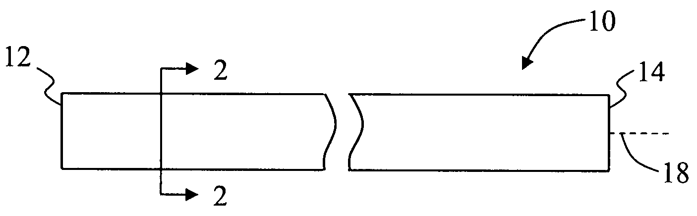
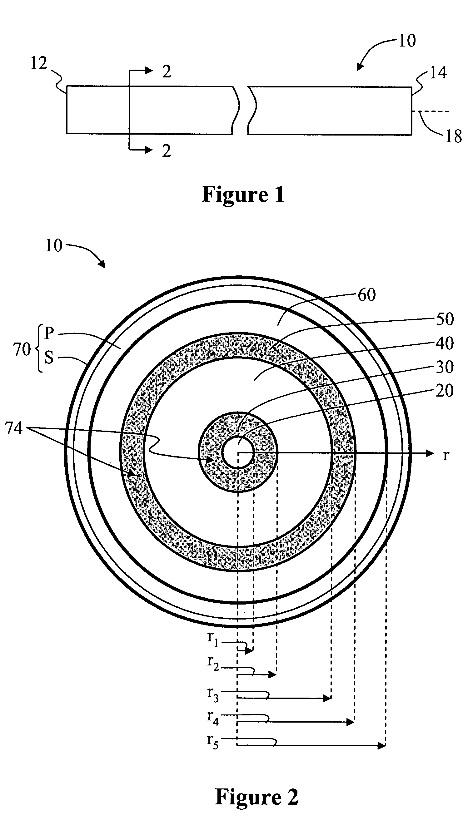
[0029]Reference will now be made in detail to the present preferred embodiments of the invention, examples of which are illustrated in the accompanying drawings. Whenever possible, the same reference numbers and symbols are used throughout the drawings to refer to the same or like parts.

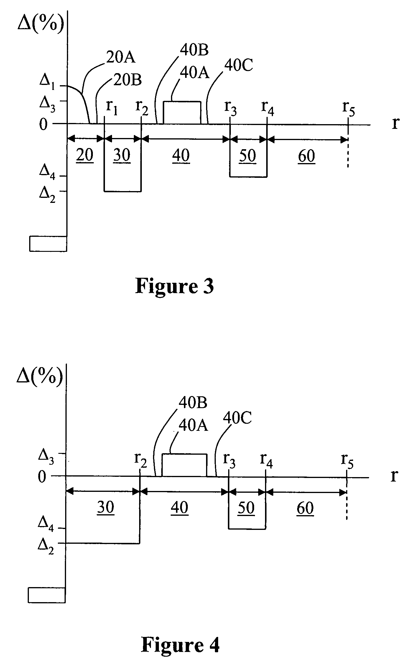
[0030]In the discussion below, the “refractive index profile” is the relationship between refractive index or relative refractive index and waveguide fiber radius. The “relative refractive index percent”is defined as Δ(%)=[(ni2−nc2) / 2ni2]×100, where ni is the maximum refractive index in region i, unless otherwise specified, and nc is the average refractive index of the cladding region, as discussed below. As used herein, the relative refractive index percent is represented by Δ(%) and its values are given in units of “%”, unless otherwise specified or as is apparent by the context of the discussion. As used herein, “Δ(%)” refers to relative refractive index percent at a wavelength of 1550 nm.

[0031]In...


PUM

PropertyMeasurementUnit
widthaaaaaaaaaa
radiusaaaaaaaaaa
diameteraaaaaaaaaa

Abstract

An optical fiber adapted to carry optical power for powering an electrical device and also optionally adapted to carry optical data for signal processing. The optical fiber capable of carrying both optical data and optical power includes a central data waveguide region that carries data light and an annular power waveguide region concentrically surrounding the data waveguide region and adapted to carry relatively large amounts of optical power. A first annular isolation region between the data and power waveguide regions and that includes microstructures serves to optically isolate the waveguide regions. An outer annular isolation region serves to confine power light to the power waveguide region and contributes to the bend-resistance of the optical fiber. An optical power and optical data distribution system that utilizes the optical fiber is also described.

Description

CROSS-REFERENCE TO RELATED APPLICATIONS[0001]This application claims the benefit of, and priority of U.S. Provisional Patent Application No. 60 / 927,977 filed on May 7, 2007, the content of which is relied upon and incorporated herein by reference in its entirety.BACKGROUND OF THE INVENTION[0002]1. Field of the Invention[0003]The present invention relates generally to optical fibers, and in particular to an optical fiber capable of transmitting optical power or both optical power and optical data.[0004]2. Technical Background[0005]Powering electrical devices (including electronic devices) using copper wires is problematic in certain environments where electrical isolation is required. For example, in high-voltage power distribution lines, the copper wire connecting the ground station to the current-sensing system located at the top of the high-voltage line requires a complex, bulky and heavy isolation system, which is eliminated if the sensor is driven using a fiber system.[0006]Due ...

Claims


Application Information

Patent Timeline
Patent Type & Authority Applications(United States)
IPC IPC(8): G01J1/44G02B6/02G02B6/036
CPCG02B6/02047G02B6/02333G02B6/02357G02B6/02361G02B6/03666H04B10/807
Inventor BOOKBINDER, DANA CRAIGCOON, JEFFREYDAINESE, JR., PAULO CLOVISLI, MING-JUNTANDON, PUSHKAR
Owner CORNING INC
Why Eureka
Try Eureka