Cladding light stripper and method of manufacturing

a technology of cladding light stripper and manufacturing method, which is applied in the field of optical fiber devices, can solve the problems of limited power handling capability of index-matching cladding light stripper b>10/b>a, limited optical power scalability, and difficult scaling up of cladding light power using high-index or index-matched layers. achieve the effect of high optical power level

Active Publication Date: 2014-07-31
LUMENTUM OPERATIONS LLC
View PDF18 Cites 56 Cited by
  • Summary
  • Abstract
  • Description
  • Claims
  • Application Information

AI Technical Summary

Benefits of technology

[0013]A cladding stripper of the invention includes a plurality of transversal notches or grooves in an outer surface of an inner cladding of a double clad optical fiber. Advantageously, position and orientation of the notches can be selected to even out cladding light release along the cladding light stripper, enabling a more even temperature distribution due to released cladding light. Furthermore, a cladding stripper can be made polymer-free, thus allowing scaling to high optical power levels.

Problems solved by technology

For high-power fiber sources, more than 300 W of cladding light may be present, and safely and efficiently removing this light represents a significant technological challenge.
The index-matching cladding light stripper 10A can sometimes achieve good efficiency of stripping cladding light, yet its optical power scalability is limited by the highest temperature the high-index polymer layer 15 can handle, typically in the range of 100° C. to 150° C. Scaling up cladding light power using high-index or index-matched layers is challenging and limited, because using high index polymer to strip out the light has no or little ability to control stripping rate.
Hence, the power handling capability of the index-matching cladding light stripper 10A is limited by localized heating.
When the polymer overheats due to absorption of released cladding light, its refractive index decreases, thereby limiting the local release of light from the cladding and the resultant heating, causing the cladding light to be released at some location downstream of the overheated point.
The low NA light is difficult to remove with polymer based cladding light strippers, since the strip rate of these strippers is very sensitive to NA of the light.
Heat load of polymer based cladding light strippers is highly non-uniform, and extra length must be used to achieve desired strip rate for the low NA cladding light.
Detrimentally, most of the cladding light is stripped in the upstream portion of the cladding stripper, creating uneven temperature distribution in the stripper.
Furthermore, roughening the surface may generate micro-cracks that can propagate over time and cause the fiber to fail.

Method used


Image

  • Cladding light stripper and method of manufacturing
  • Cladding light stripper and method of manufacturing
  • Cladding light stripper and method of manufacturing

Examples


Embodiment Construction

[0044]While the present teachings are described in conjunction with various embodiments and examples, it is not intended that the present teachings be limited to such embodiments. On the contrary, the present teachings encompass various alternatives and equivalents, as will be appreciated by those of skill in the art.

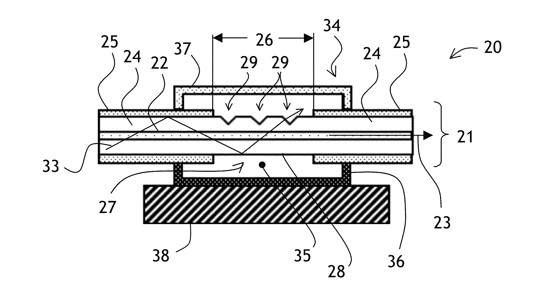
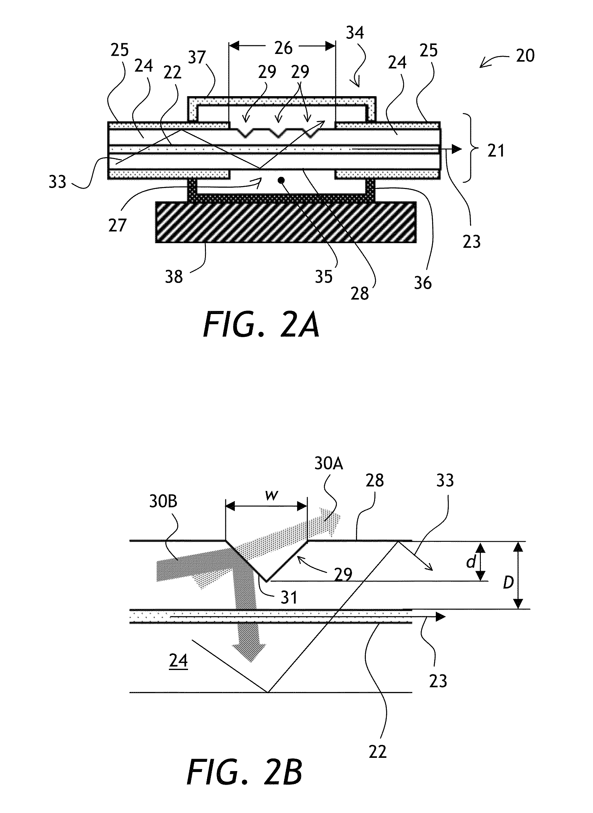
[0045]Referring to FIGS. 2A and 2B, a cladding light stripper 20 includes a double-clad optical fiber 21 having a core 22 for guiding signal light 23, an inner cladding 24 surrounding the core 22, and an outer cladding 25 surrounding the inner cladding 24. The optical fiber 21 includes a stripped portion 26 wherein the outer cladding 25 is removed, forming an exposed section 27 of an outer surface 28 of the inner cladding 24. Thus, the stripped portion 26 is absent the outer cladding 25. The exposed section 27 includes a plurality of transversal notches 29 disposed along the fiber 21 in the exposed section 27 of the outer surface 28 of the inner cladding 24 to enable cl...


PUM

PropertyMeasurementUnit
depthsaaaaaaaaaa
lengthaaaaaaaaaa
bend radiusaaaaaaaaaa

Abstract

A cladding stripper includes a plurality of transversal notches or grooves in the outer surface of an exposed inner cladding of a double clad optical fiber. Position and orientation of the notches can be selected to even out cladding light release along the cladding light stripper, enabling more even temperature distributions due to released cladding light. The notches on the optical fiber can be made with a laser ablation system.

Description

CROSS REFERENCE TO RELATED APPLICATIONS[0001]The present invention claims priority from U.S. Patent Application No. 61 / 757,434 filed Jan. 28, 2013, which is incorporated herein by reference.TECHNICAL FIELD[0002]The present invention relates to optical fiber devices and related methods, and in particular to devices and methods for removing cladding light in fiber amplifiers and lasers.BACKGROUND OF THE INVENTION[0003]Fiber lasers are an important new class of lasers that provide significant advantages of efficiency and practicality in comparison with other laser types such as free-space lasers. With the advent of a double-clad fiber (DCF), fiber lasers have been scaled to kilowatt (kW) power levels. In a DCF, pump light propagates in a relatively large inner cladding, typically 125 to 600 micrometers in diameter, and the laser light propagates in the much smaller core, typically 5 to 100 micrometers in diameter. The core is doped with ions of a rare-earth element, such as Ytterbium, ...

Claims


Application Information

Patent Timeline
Patent Type & Authority Applications(United States)
IPC IPC(8): H01S3/094B29D11/00G02B6/26
CPCH01S3/094007G02B6/14G02B6/264B29D11/00663H01S3/06733G02B6/02342H01S3/06708G02B6/02066G02B6/2852B23K26/0622B23K26/0626B23K26/36H01S3/06729H01S3/0941
Inventor HOU, KAI-CHUNGKLINER, DAHVMUENDEL, MARTIN H.WESTON, JEREMY
Owner LUMENTUM OPERATIONS LLC
Why Eureka
Try Eureka