Laser beam processing machine

A laser beam and processing machine technology, applied in metal processing, laser welding equipment, metal processing equipment, etc., can solve problems such as unsatisfactory productivity and achieve the effect of high-efficiency laser beam processing

Inactive Publication Date: 2005-10-19
DISCO CORP
View PDF2 Cites 13 Cited by
  • Summary
  • Abstract
  • Description
  • Claims
  • Application Information

AI Technical Summary

Problems solved by technology

[0011] However, since in the processing method of the above-mentioned plate-shaped workpiece, among the plurality of processing lines formed on the workpiece held on the chuck table, along the processing line just before the processing line along which the laser processing is being performed, Detects the height position of the surface to be processed, so laser beam processing is not performed simultaneously along the processing line whose height position has been detected first, and thus is unsatisfactory in terms of productivity

Method used


Image

  • Laser beam processing machine
  • Laser beam processing machine
  • Laser beam processing machine

Examples


Embodiment Construction

[0026] Preferred embodiments of the present invention will be described in detail below with reference to the accompanying drawings.

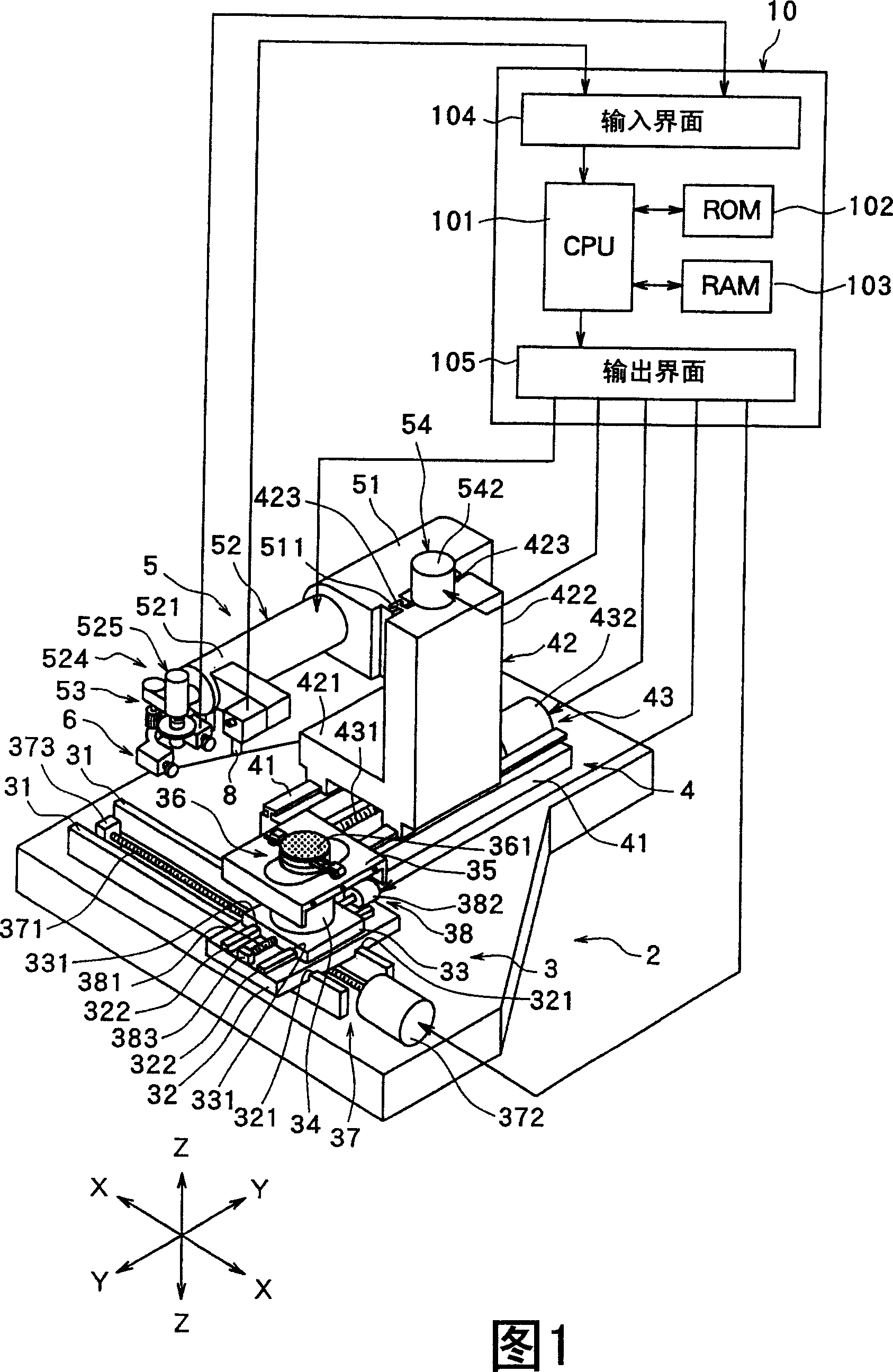
[0027] Figure 1 is a perspective view of a laser beam processing machine constructed in accordance with the present invention. The laser beam processing machine shown in Fig. 1 comprises a stationary base 2, a chuck table mechanism 3 for holding a plate-shaped workpiece, a laser beam applying unit supporting mechanism 4, and a laser beam applying unit 5, wherein the chuck table mechanism 3 is Mounted on the stationary base 2 in a manner that can move along the processing feed direction indicated by the arrow X, the laser beam applying unit support mechanism 4 can be moved along the direction indicated by the arrow Y in the direction perpendicular to the direction indicated by the arrow X. It is installed on the stationary base 2 in a manner of moving in the direction of 100°, and the laser beam applying unit 5 is installed on the support mechan...


PUM

PropertyMeasurementUnit
diameteraaaaaaaaaa
thicknessaaaaaaaaaa
wavelengthaaaaaaaaaa

Abstract

A laser beam processing machine comprising a chuck table having a workpiece holding surface for holding a plate-like workpiece, a laser beam application means having a condenser for applying a laser beam from the top surface side of the workpiece held on the chuck table to form a focusing point, and a focusing point position adjusting means for moving the focusing point formed by the condenser in a direction perpendicular to the workpiece holding surface, wherein the machine further comprises a height position detection means for detecting the height position of an area to which a laser beam is applied from the condenser of the top surface of the workpiece held on the chuck table, and a control means for controlling the focusing point position adjusting means based on the height position detection signal of the height position detection means.

Description

technical field [0001] The present invention relates to a laser beam processing machine for performing laser processing along a predetermined processing line on a plate-like workpiece held on a chuck table. Background technique [0002] In the production process of a semiconductor device, a plurality of regions are divided according to dividing lines called "streets" arranged in a lattice pattern provided on the front surface of a substantially disk-shaped semiconductor wafer, and in each divided region, such as IC , LSI and other circuits. Individual semiconductor chips are manufactured by dicing the semiconductor wafer along boundary lines to divide it into regions on which circuits are formed. Also, wafers containing optical devices such as gallium nitride-based compound semiconductors laminated on the front surface of a sapphire substrate are diced along the dividing line to separate individual optical devices such as light-emitting diodes or laser diodes widely used in...

Claims


Application Information

Patent Timeline
Patent Type & Authority Applications(China)
IPC IPC(8): B23K26/03B23K26/10B23K26/40H01L21/301H01L21/304
CPCB23K26/4075B23K2201/40B23K26/034B23K26/0853B23K26/03B23K26/032B23K26/048B23K26/0884B23K2101/40B23K2103/50B23K26/40
Inventor 能丸圭司
Owner DISCO CORP
Why Eureka
Try Eureka