Centering joining tooth type coaptation plate

A technology of bone plate and tooth shape, applied in the direction of outer plate, inner bone synthesis, internal fixator, etc., to achieve the effect of enhancing anti-slip, convenient bundling and reset, and promoting the formation of callus

Inactive Publication Date: 2005-10-26
张荣魁 +1
View PDF2 Cites 6 Cited by
  • Summary
  • Abstract
  • Description
  • Claims
  • Application Information

AI Technical Summary

Problems solved by technology

[0011] The present invention aims to overcome the deficiencies and defects of the existing osteosynthesis plate, and aims to provide a centripetal bone plate suitable for the requirements of various fracture anatomical structures, simple in structure, strong in functionality, capable of meeting fracture treatment requirements, and stable in treatment effect. Hook tooth bone plate

Method used


Image

  • Centering joining tooth type coaptation plate
  • Centering joining tooth type coaptation plate
  • Centering joining tooth type coaptation plate

Examples


Embodiment Construction

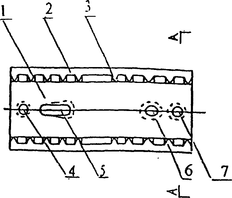
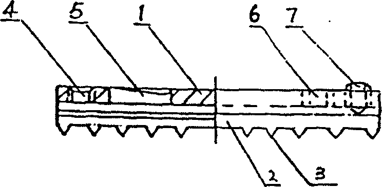
[0039] Depend on Figure 1-3 As shown, the centripetal hook-toothed bone plate includes a base plate 1 with a hook-shaped angle rib 2 with a blade tip, teeth 3 are arranged longitudinally at the blade tip of the angle rib, and there is a threaded hole 4 on the base plate 1. Close the reset adjustment hole 5, the pressure screw installation hole 6, and adjust the top screw 7.

[0040] The hook-shaped ribs 2 with blade tips are located at both ends of the concave bone-attached surface of the base plate 1 or around the outer edge of the bone plate, and at least one tooth 3 is arranged along the distance between the blade tips of the longitudinal ribs.

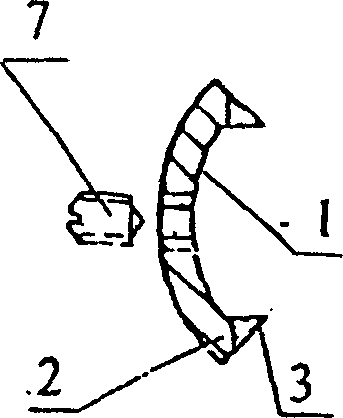
[0041] Depend on Figure 4 As shown, A, B are the two ends of the outer arc of the base plate 1, E, F are the two ends of the inner arc of the base plate 1, C, D are the two occlusal points of the blade tip and the bone skin, G, the bone skin of the outer diameter of the bone line, O is the bone center point. H is the centerlin...


PUM


Abstract

A bone-setting plate with centripetal hook teeth for treating bone fracture is composed of an arch base plate with arc cross-section, screwed holes, pressing screw installing holes and bone regulating holes, the hook-shaped angular ribs with cutting tip, and the teeth arranged at the cutting tip of longitudinal angular rib at intervals.

Description

technical field [0001] The invention relates to a medical bone plate for treating human body fractures, in particular to a hook-shaped bone plate. Background technique: [0002] At present, the AO series of traditional bone plates are widely used in the treatment of fractures in various parts of the human body. This bone plate has a smooth bone-adhering surface, which is characterized by a large area of ​​contact with the outer surface of the bone after fixation. As a result, undesirable phenomena arise. [0003] 1. The outer layer of human bones is a smooth surface, while the traditionally used bone plate is also a smooth surface with a high degree of finish. The two smooth surfaces form a sliding and free state, making it difficult to locate the fracture connection surgery. In order to achieve the purpose of strong fixation, the torque of the fixing screw must be increased. If the torque is too large, the screw and the bone will be disconnected. Du...

Claims


Application Information

Patent Timeline
Patent Type & Authority Applications(China)
IPC IPC(8): A61B17/68A61B17/80
CPCA61B17/809A61B17/8004
Inventor 张荣魁夏元海
Owner 张荣魁
Why Eureka
Try Eureka