
Method for detecting position displacement of cutting blades

A cutting blade and detection method technology, which is applied in semiconductor/solid-state device testing/measurement, electrical components, semiconductor/solid-state device manufacturing, etc., can solve the problem of inability to correctly measure the position deviation of cutting blades, and achieve the goal of preventing miscutting Effect

Active Publication Date: 2005-11-02
DISCO CORP
View PDF1 Cites 7 Cited by
  • Summary
  • Abstract
  • Description
  • Claims
  • Application Information

AI Technical Summary

Problems solved by technology

Thus, since the grooves formed on the adhesive tape by overrun do not coincide with the grooves on the surface of the semiconductor wafer, the positional deviation of the cutting blade cannot be accurately measured based on the grooves formed on the adhesive tape.
The above problems also occur in the case of cutting plate-shaped objects other than semiconductor wafers.

Method used


Image

  • Method for detecting position displacement of cutting blades
  • Method for detecting position displacement of cutting blades
  • Method for detecting position displacement of cutting blades

Examples


Embodiment Construction

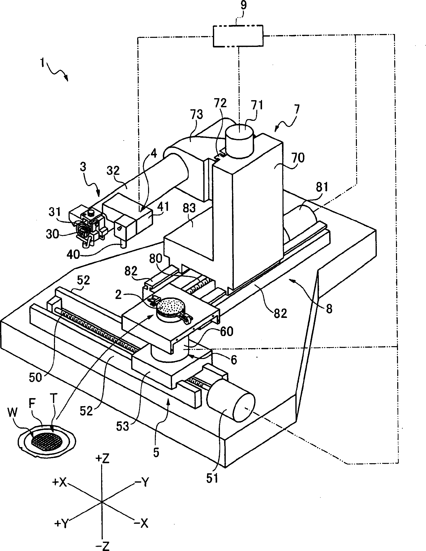
[0025] figure 1 The cutting device 1 shown is an example of the device used in the embodiment of the present invention, and is equipped with a suction cup table 2 holding a plate-shaped object, and a cutting blade 31 for cutting a plate-shaped object held on the suction cup table 2. The cutting mechanism 3 and the alignment mechanism 4 that have an optical system 40 that forms a reference line for positioning and can detect a planned cutting area of ​​a plate-shaped object.

[0026] The suction cup table 2 can be moved in the X-axis direction by the X-axis feed mechanism 5 and can be rotated by the rotary drive mechanism 6 at the same time. The chuck table feeding mechanism 5 is composed of a ball screw 50 arranged in the X-axis direction, a driving source 51 connected to one end of the ball screw 50 to rotate the ball screw 50 , and a pair of ball screws arranged parallel to the ball screw 50 . A guide rail 52 and a movable base 53 that is slidably engaged with the guide rai...


PUM


Abstract

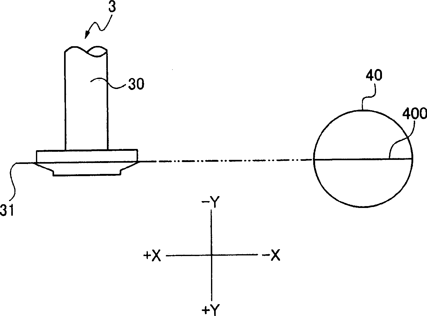
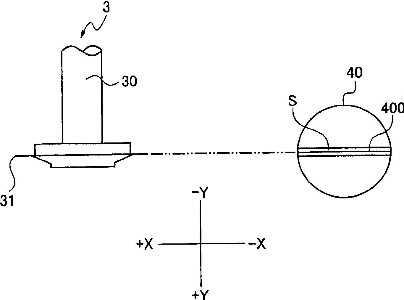
The objective is to exactly cut a desired position by exactly detecting the misregistration of a cutting blade in a cutting apparatus so as to prevent erroneous cutting. On the premise that a base line 400 and the cutting blade coincide with each other, an area to be cut and the base line 400 are made to coincide with each other. In a state that the base line 400 is made to coincide with the area to be cut, an objective area is cut. While index-feeding a cutting means by each space of the objective area, a plurality of the objective areas are cut. In addition to the cutting of a sheet-like matter, a cut flaw 100 is formed by making the cutting blade cut in a sheet-like matter absence area T1 to detect the positional displacement of the cut flaw 100 and the base line 400 by detecting the flaw 100 by an alignment means.

Description

technical field [0001] The present invention relates to a method for detecting positional displacement of a cutting insert mounted on a cutting device. Background technique [0002] A semiconductor wafer divided by channels to form a plurality of semiconductor devices is divided into individual semiconductor chips by cutting the channels with a cutting blade constituting a dicing device, and used for various electronic devices. [0003] In the dicing device, the semiconductor wafer is held on the chuck table, the channel to be cut is detected, and after positioning (alignment) between the channel and the cutting blade, the high-speed rotating cutting blade cuts into the channel for cutting. Since the cutting insert is installed on the spindle, the thermal expansion caused by the high-speed rotation of the spindle will cause the position of the cutting insert to shift. Also, due to the positional deviation, the cutting blade may cut to a position deviated from the channel, t...

Claims


Application Information

Patent Timeline
Patent Type & Authority Applications(China)
IPC IPC(8): H01L21/301H01L21/66
Inventor 根岸克治松本航平木佐贯诚
Owner DISCO CORP
Learn More