Tool grinding machine

A tool grinding machine and tool technology, which is used in grinding machines, manufacturing tools, grinding machine beds, etc., can solve problems such as increased scrap rate, tool blade grinding angle not on the correct specific surface, and reduced work efficiency.

Inactive Publication Date: 2005-11-02
金明珍
View PDF0 Cites 17 Cited by
  • Summary
  • Abstract
  • Description
  • Claims
  • Application Information

AI Technical Summary

Problems solved by technology

Therefore, there is a problem that the grinding angle of the tool blade is not on the correct specific face, thereby reducing work efficiency
In particular, if an incorrect insert angle is created during the grinding process, as in an end mill, when the tool is mounted on the machine, the wrong plane will be machined, resulting in an increased scrap rate

Method used


Image

  • Tool grinding machine
  • Tool grinding machine
  • Tool grinding machine

Examples


Embodiment Construction

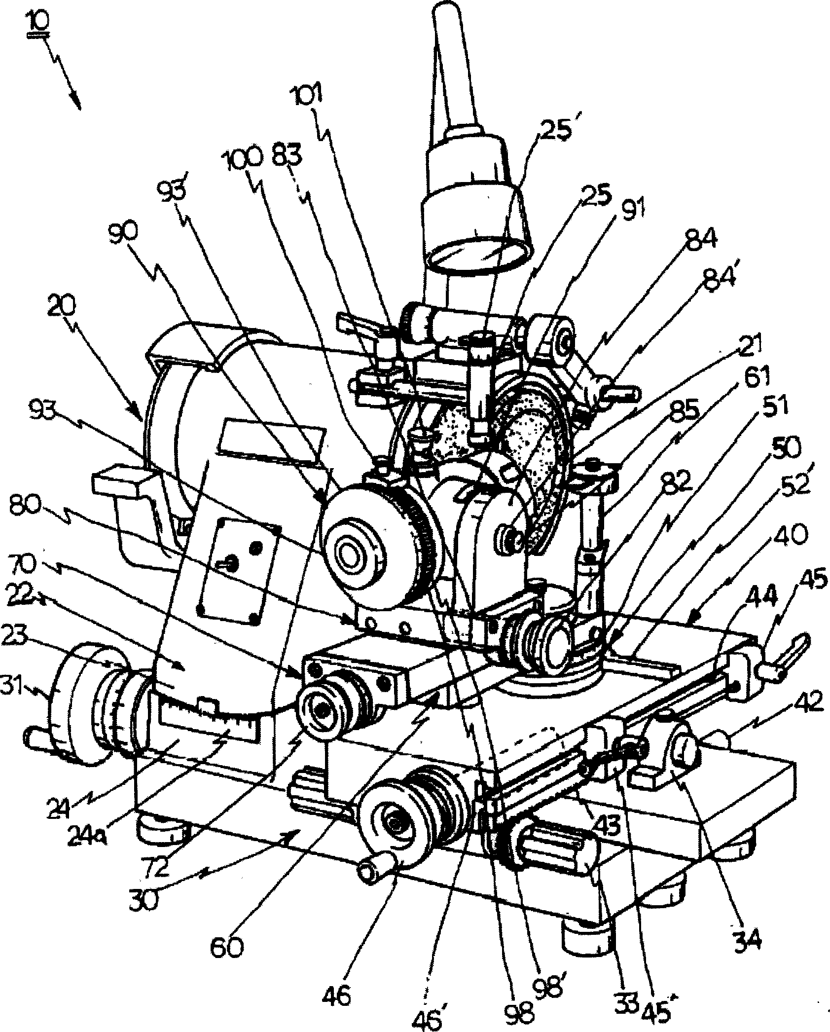
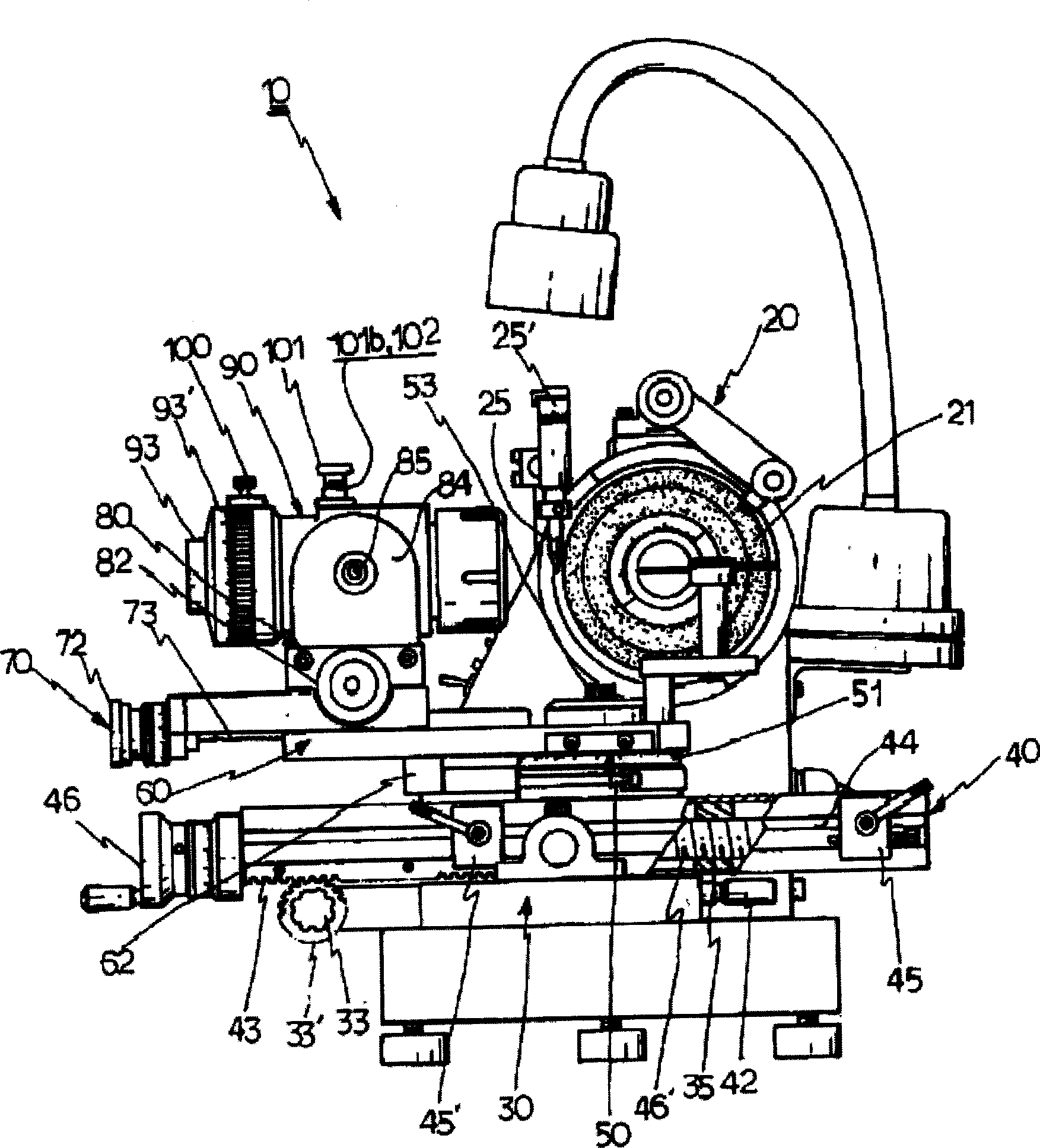
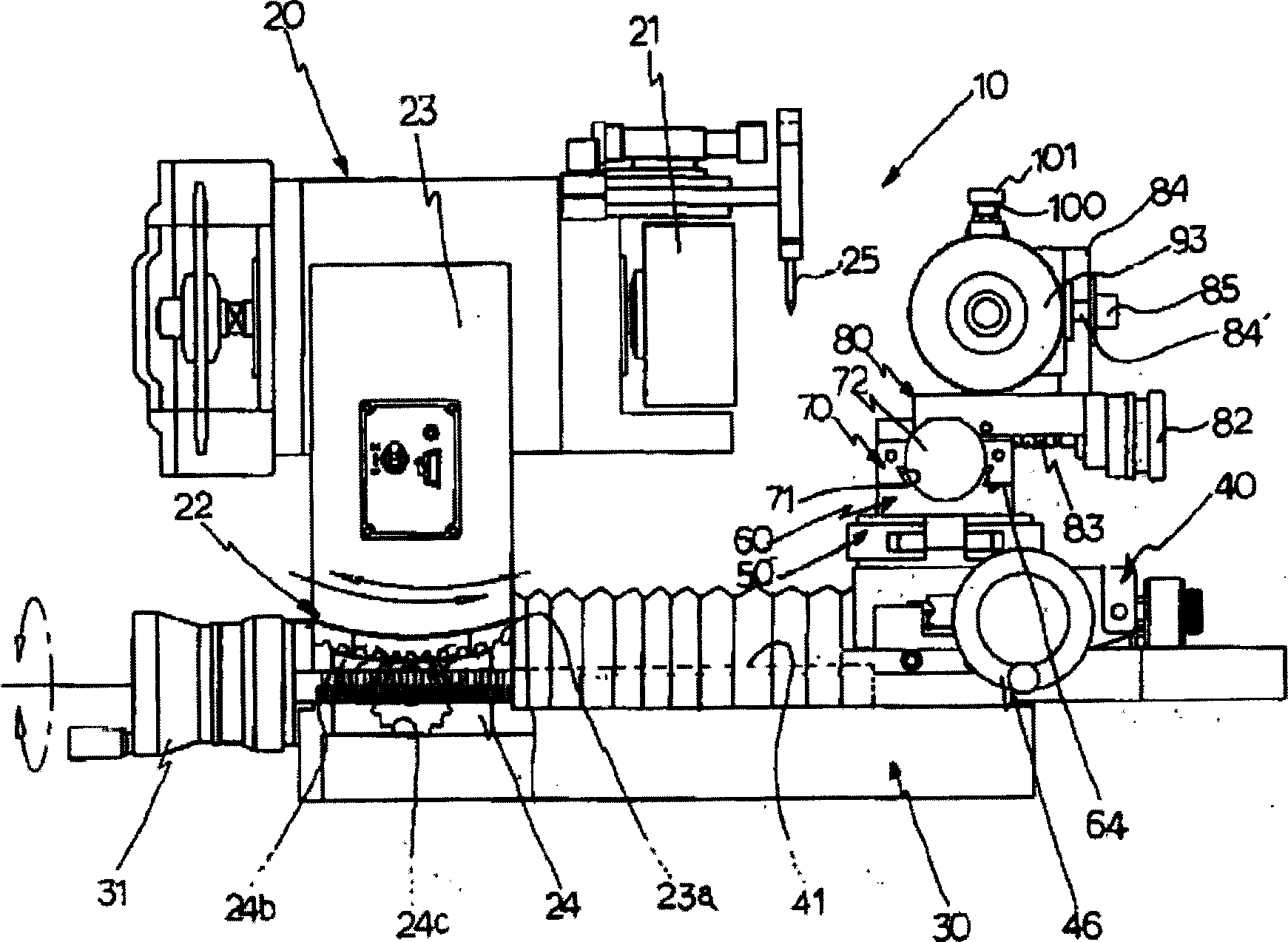
[0030] Hereinafter, the present invention will be described in detail with reference to the accompanying drawings.

[0031] A whetstone 21 driven by a driving motor (not shown) is provided at an axial end of the grinding portion 20 inside the main body 10 . Below the grinding part 20, a relief angle adjusting member 22 is arranged, and the relief angle adjusting member 22 is divided into an upper rotating member 23 and a lower fixing member 24, wherein an arc-shaped relief angle scale plate 24a is arranged in front of the fixing member 24 , and a plurality of bolts 24b are engaged with the back of the fixing member 24, wherein, after setting the relief angle value of the rotating member by opening the rotating member 23, the rotating member 23 can be fixed by bolts. Between the rotating member 23 and the fixing member 24, an arc-shaped rack 23a is formed in the rotating member 23, and a spur gear 24c is formed in the fixing member 24, so that the rotating member 23 can rotate ...


PUM


Abstract

The present invention relates to a tool grinding machine. That is, the present invention is characterized in that a hinge is formed at the center of a body of a chuck holder and a slope scale plate is attached to a top of the hinge such that an angle of a under blade of a tool such as an end mill is accurately ground, the first and second angles of the peripheral cutting blade of the tool are simultaneously ground using an angle adjustment lever in an end of the chuck holder, in an angle scale plate at a rotation portion a fixed block gauge is again adhered to a sin value of a desired angle using the fixed block gauge as a reference, thereby accurately grinding the under blade of the tool and the first and second angles of the peripheral cutting blade, a body of the grinding portion is divided into upper and lower portions so that the upper body is rotated in a desired angle and at the same time, and an angle scale plate is formed so that a worker checks up the angle in the rotation state, thereby forming a spherical angle of the tool.

Description

technical field [0001] The present invention relates to tool grinding machines. Background technique [0002] Generally, when a tool mounted on a machine wears a blade of the tool during use, or when a new tool is installed on the machine, a grinder is used to grind the blade of the tool. In a traditional grinding machine, the feed plate of the bed can move forward, backward, left, and right, and a rotating part is provided on the feed plate to rotate the chuck frame holding the tool. By moving and rotating the chuck frame, the tool reaches the optimal grinding position of the object installed on the grinding part, so as to grind the blade of the tool. However, in order to use the above method to grind a tool, it is necessary to use the skill of the worker to perform a series of task operations to adjust the grinding angle, that is, to rotate the chuck frame holding the tool relative to the object, so that the tool can be kept properly ground. angle. Therefore, there is a...

Claims


Application Information

Patent Timeline
IPC IPC(8): B24B3/06B24B19/04B24B41/02B24B41/06
CPCB24B3/06B24B19/04B24B41/02B24B41/067
Inventor 金明珍
Owner 金明珍
Why Eureka
Try Eureka