Bipolar plate of fuel cell

A fuel cell and bipolar plate technology, applied in the direction of fuel cells, fuel cell parts, fuel cell additives, etc., can solve the problem of increasing the flow resistance of fuel and air flow, poor fluid flow distribution, and inappropriate use of the first Bipolar plate, etc.

Inactive Publication Date: 2005-11-02
LG ELECTRONICS INC
View PDF0 Cites 19 Cited by
  • Summary
  • Abstract
  • Description
  • Claims
  • Application Information

AI Technical Summary

Problems solved by technology

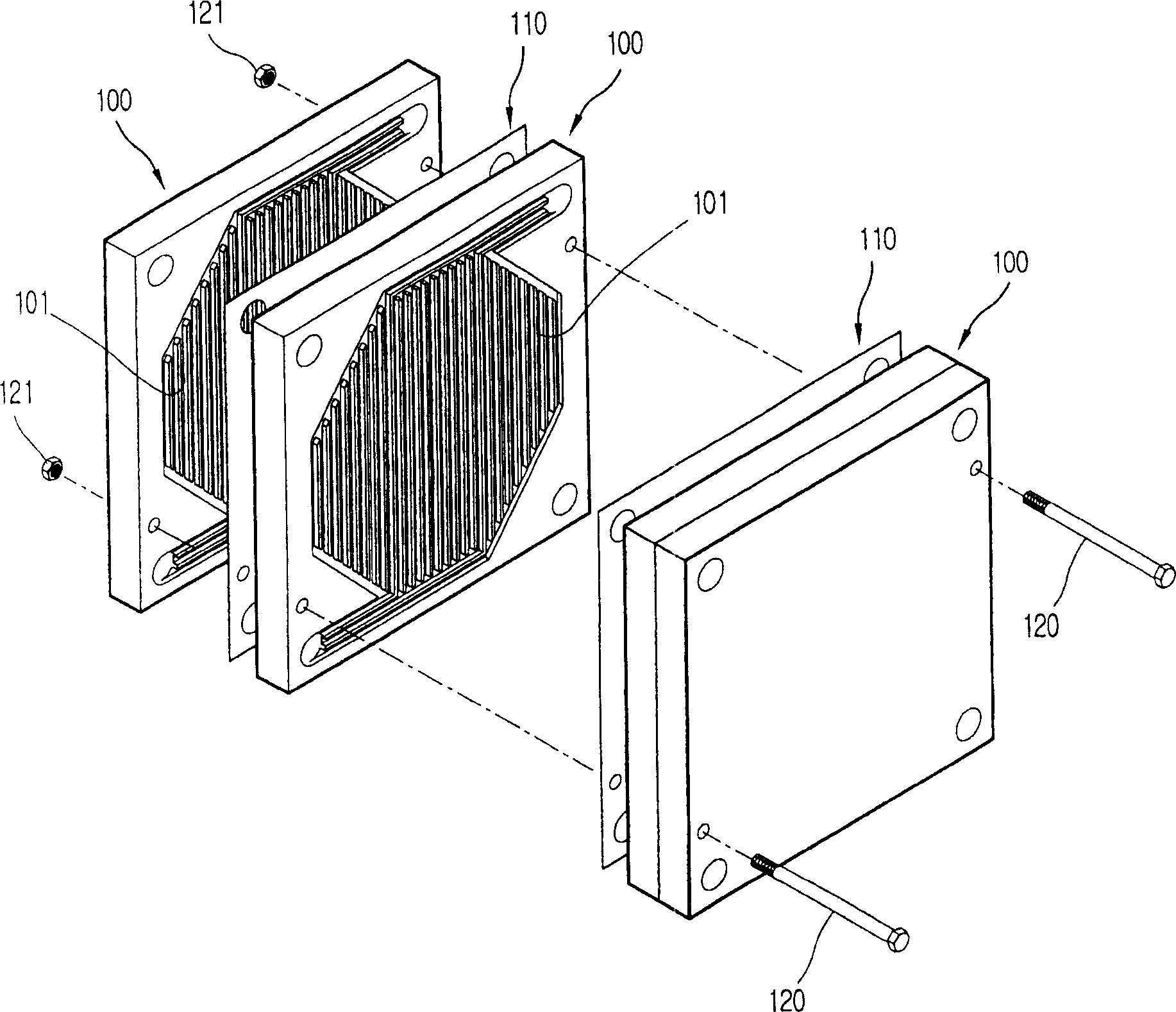
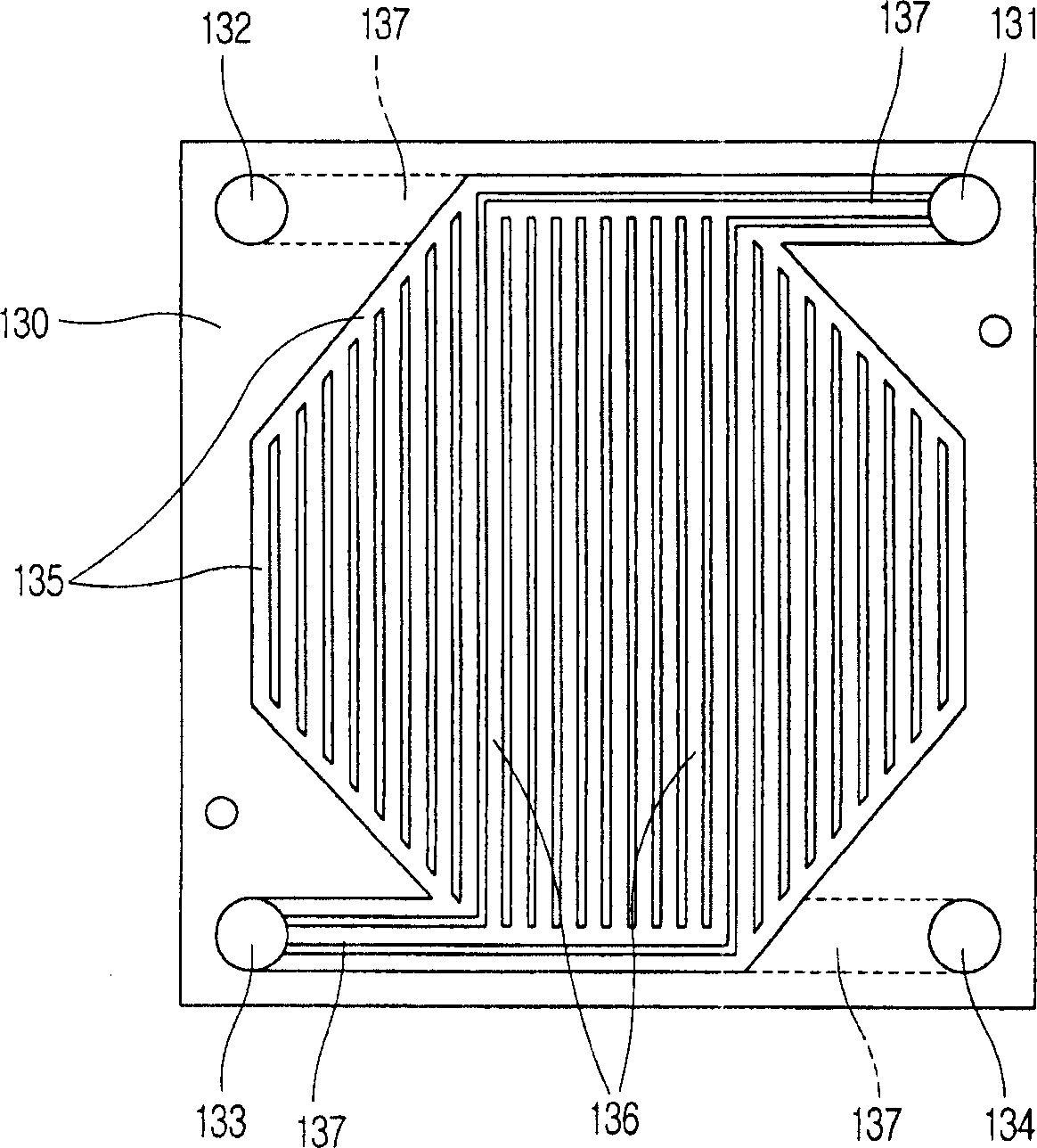
[0013] However, in the conventional first bipolar plate, because compared with the number of straight channels 136 formed in the hexagonal channels, for connecting the through holes 131, 132, 133, 134, the hexagonal channels 135 and the straight channels The quantity of the connecting channel 137 of the channel 136 is very small, so the flow distribution of the fluid flowing into

Method used


Image

  • Bipolar plate of fuel cell
  • Bipolar plate of fuel cell
  • Bipolar plate of fuel cell

Examples


Embodiment Construction

[0035] Next, preferred embodiments of the fuel cell bipolar plate according to the present invention will be described with reference to the accompanying drawings.

[0036] First, a first embodiment of the bipolar plate of the fuel cell according to the present invention will be described.

[0037] Figure 5 is a plan view illustrating a first embodiment of a fuel cell bipolar plate according to the present invention, Figure 6 is along Figure 5 The cross-sectional view taken from A-B in the middle.

[0038] Such as Figure 5 and 6 As shown, the fuel cell bipolar plate according to the present invention includes: a pole plate 150 with a certain area and thickness; inflow and outflow buffer grooves 151, 152 respectively formed on both sides of the pole plate 150 to have a certain area and depth; A plurality of channels 153 for connecting the inflow buffer tank 151 and the outflow buffer tank 152; formed on the pole plate 150 to connect the inflow path 154 of the inflow bu...


PUM


Abstract

In a bipolar plate of a fuel cell including a plate having a certain area and thickness; inflow and outflow buffer grooves respectively formed at both sides of the plate so as to have a certain area and depth; plural channels for connecting the inflow buffer groove and the outflow buffer groove; plural buffer protrusions formed in the inflow and outflow buffer grooves so as to have a certain height; an inflow path formed on the plate so as to be connected to the inflow buffer groove; and an outflow path formed on the plate so as to be connected to the outflow buffer groove, it is possible to uniformize flux distribution and reduce flow resistance of fuel and air respectively flowing into a fuel electrode and an air electrode of a fuel cell.

Description

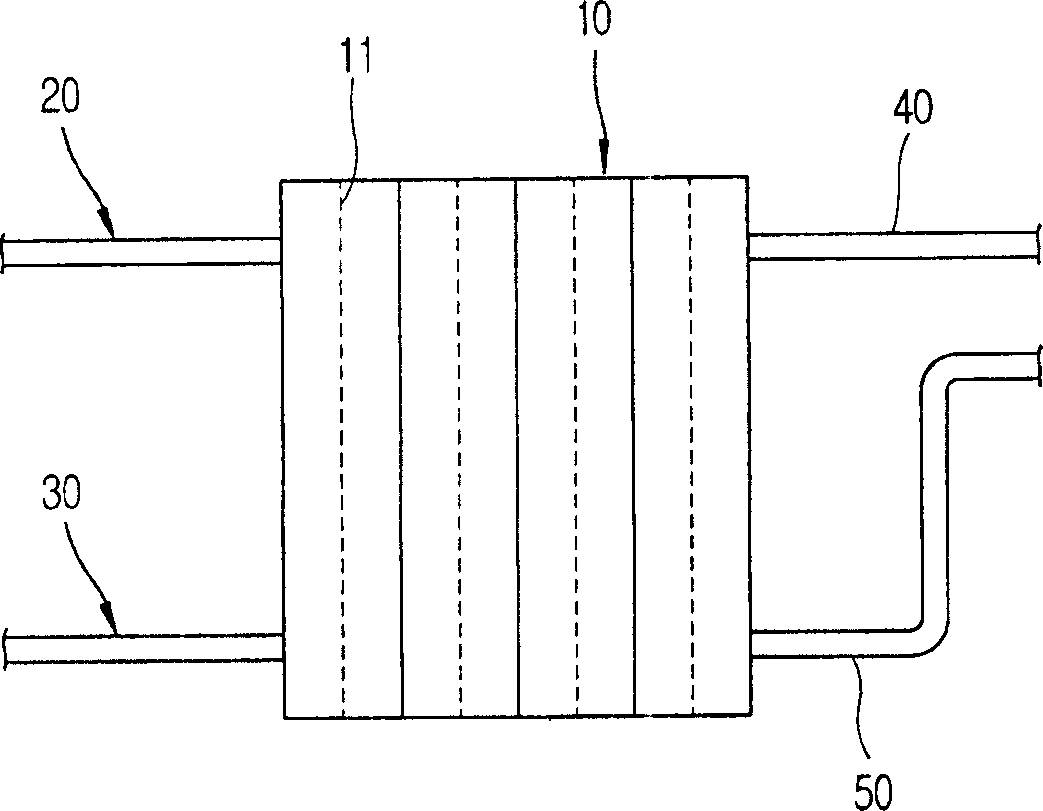
technical field [0001] The present invention relates to a fuel cell, and more particularly to a fuel cell bipolar plate capable of homogenizing flow distribution and reducing the flow resistance of fuel and air flowing into a fuel electrode (anode) and an air electrode (cathode) of the fuel cell, respectively. Background technique [0002] Fuel cells are generally environmentally friendly energy, and fuel cells have been developed to replace conventional fossil (fossil) energy. Such as figure 1 As shown, the fuel cell includes: a cell stack combined with at least one unit cell 11 in which an electrochemical reaction occurs; a fuel supply pipe 20 connected to the cell stack 10 to supply fuel; an air tube connected to the cell stack 10 to supply air supply pipe 30; and discharge pipes 40, 50 for discharging by-products of reacted fuel and air, respectively. The unit cell 11 includes a fuel electrode (anode) (not shown) in which fuel flows and an air electrode (cathode) (not ...

Claims


Application Information

Patent Timeline
IPC IPC(8): H01M8/02H01M8/04
CPCH01M8/0247Y02E60/50H01M8/0258H01M8/0265H01M8/2483H01M8/026
Inventor 赵泰熙朴明硕崔弘金奎晸李明浩金铁焕黄龙俊高承兑许成根
Owner LG ELECTRONICS INC
Why Eureka
Try Eureka