Implant for fixing bones

An implant and fixation technology, applied in the field of implants

Inactive Publication Date: 2010-07-14
SYNTHES GMBH
View PDF5 Cites 0 Cited by
  • Summary
  • Abstract
  • Description
  • Claims
  • Application Information

AI Technical Summary

Problems solved by technology

However, metal plates are too rigid and less rigid plastic plates, especially those made of absorbable plastic, are too weak
In addition, problems arise when the plastic plate is connected to the metal bone screw, especially if the connection is not locally stable.

Method used


Image

  • Implant for fixing bones
  • Implant for fixing bones
  • Implant for fixing bones

Examples


Embodiment Construction

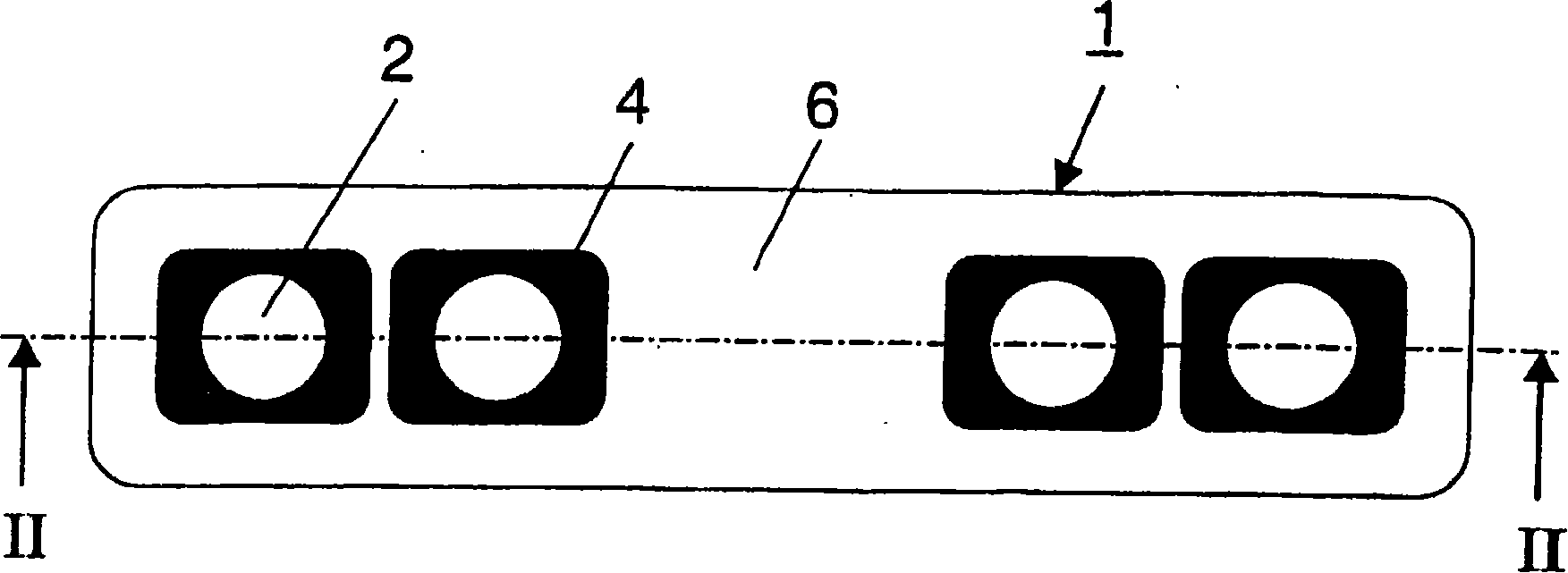
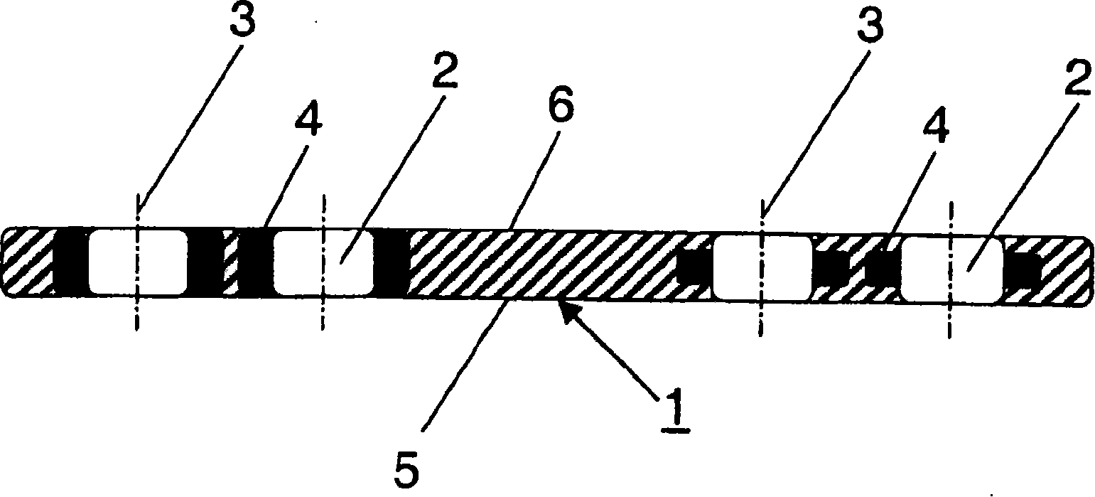
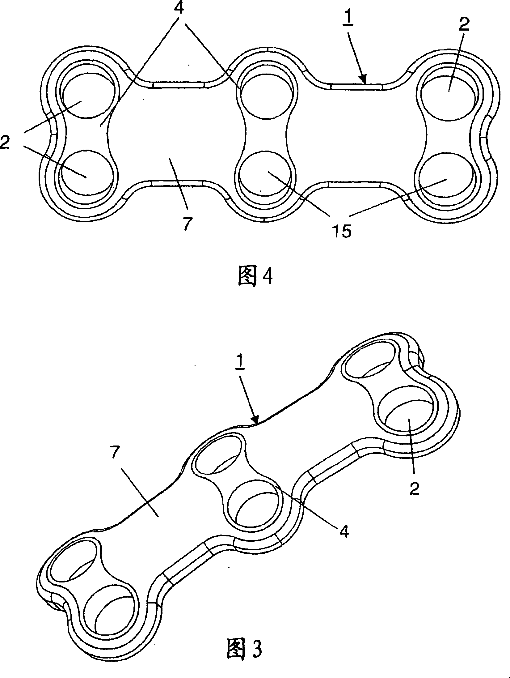
[0028] in figure 1 with figure 2 The implant 1 shown in is a bone plate, which is basically composed of a biocompatible plastic such as polyetheretherketone (PEEK) and has four circular holes in the form of channels 2 with axis 3 for Accommodate bone screws (not shown in the figure). The channel 2 connects the bottom surface 5 of the bone plate for abutting on the bone and the top surface 6 thereof.

[0029] In this case, the channel 2 is embedded in the form of some rectangular metal small plates, which can be understood as the outer envelope part 4 of the channel 2. For example, the outer envelope part 4 made of titanium can be embedded in the surrounding plastic material 7 (for example, PEEK) in a form-locking manner and fixedly connected with the plastic material 7 by injection molding according to its manufacturing method.

[0030] A variation of the outer envelope part 4 embedded in the plastic material 7 is shown in figure 2 On the right, in this form, the height of the ...


PUM


Abstract

Disclosed is an implant for fixing bones, which is made of a combination of metal and plastic. Said implant comprises several passages that have axes and receive a bone-fixing means, especially a bone screw. The passages are provided with a peripheral border made of a material that is different from the material of the implant, which surrounds the border. Said structure creates an implant that isless stiff and does not pose any problems concerning the screw-implant interface.

Description

technical field [0001] The invention relates to an implant for bone fixation, in particular to a bone plate. Background technique [0002] Bone plates made of metal or metal alloys and of plastics, especially absorbable polymers, are known in the art. However, metal bone plates are too rigid and less rigid plastic plates, especially plates made of absorbable plastic, are too weak. In addition, problems arise when the plastic plate is connected to the metal bone screw, especially if the connection is not locally stable. Contents of the invention [0003] The object of the present invention is to improve this situation. The object of the invention is to create an implant which has a low stiffness. [0004] The present invention solves the above-mentioned problems by means of an implant for bone fixation, which is formed as a bone plate and consists of a combination of two materials, metal and plastic, and has at least one strip passing through the implant with an axis ...

Claims


Application Information

Patent Timeline
Patent Type & Authority Patents(China)
IPC IPC(8): A61B17/80A61B17/70
CPCA61B17/80A61B17/8052A61B17/70
Inventor C·马蒂厄R·弗里格M·斯皮奇格B·莱西曼
Owner SYNTHES GMBH
Why Eureka
Try Eureka