Fluid dispenser calibration system and method

A fluid dispenser and calibration system technology, applied in the field of fluid systems, can solve the problems of labor consumption and calibration becoming troublesome

Inactive Publication Date: 2005-11-09
TAYLOR COMML FOODSERVICE LLC
View PDF0 Cites 14 Cited by
  • Summary
  • Abstract
  • Description
  • Claims
  • Application Information

AI Technical Summary

Problems solved by technology

Calibration becomes a laborious, labor-intensive process as prior art systems require repeated manual adjustments to obtain the desired fluid volume each time

Method used


Image

  • Fluid dispenser calibration system and method
  • Fluid dispenser calibration system and method
  • Fluid dispenser calibration system and method

Examples


Embodiment Construction

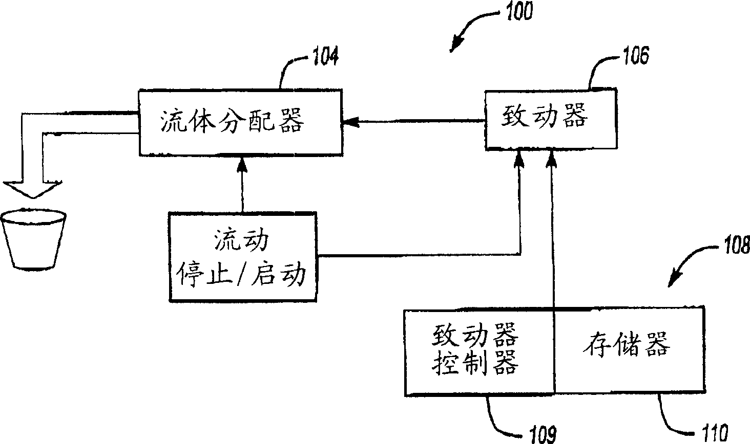
[0012] figure 1 is a schematic block diagram illustrating a fluid dispensing system 100 according to one embodiment of the present invention. System 100 includes a fluid dispenser 104 (eg, a peristaltic pump), a motor 106 or other actuator to operate fluid dispenser 104 , and a controller to control the speed of motor 106 . Controller 108 may be any known processor, actuator controller, and / or motor control device that may regulate motor or actuator speed via control signals generated, for example, pulse width modulated signals, variable voltage signals, etc. . A change in motor speed will change the operating speed of the dispenser 108 .

[0013] In one embodiment, the controller 108 includes an actuator controller 109 and a memory 110 capable of storing data of fluid dispensing time, corresponding motor speed and / or dispensing speed, and functions or algorithms related to dispensing speed, time and volume. Note that memory 110 need not necessarily be part of controller 10...


PUM


Abstract

A system and method for calibrating fluid detects an actual fluid dispensing characteristic, such as dispensing speed, and automatically adjusts the dispensing characteristic to match an ideal dispensing characteristic. The adjustment is conducted by a controller that controls fluid dispensing based on a function that correlates dispensing speed, a dispensed volume, and a dispensing time. The function allows calibration to occur automatically by converging system operation to the ideal dispensing characteristic, without requiring a user to calibrate the system through manual iterative methods.

Description

technical field [0001] The present invention relates to a fluid delivery system, and more particularly to a system that can be calibrated to dispense a predetermined volume of fluid. Background technique [0002] Many applications require fluid delivery systems to dispense fluid units having predetermined volumes. Fluid delivery systems typically use motors whose speed controls the volume of fluid dispensed at one time. For example, a peristaltic fluid delivery system includes rotating rollers that squeeze a flexible tube at selected intervals, thereby pushing approximately the same volume of fluid along the output rollers. The motor controls the speed of rotation of the rollers, thereby controlling the volume of fluid dispensed each time the rollers squeeze the flexible tube; the faster the motor speed, the greater the volume of fluid output in a given time. [0003] When the system is initially installed, or when the user wishes to change operating parameters (eg, dispen...

Claims


Application Information

Patent Timeline
Patent Type & Authority Applications(China)
IPC IPC(8): F04B13/00F04B43/12F04B49/06F04B51/00G01F11/12G01F13/00G01F25/00
CPCF04B51/00F04B13/00F04B49/065F04B2203/0209F04B2205/09G01F11/125G01F13/006F04B43/12G01F25/0092
Inventor J・J・斯科尔达托J・J・迈纳德R・罗亚迪
Owner TAYLOR COMML FOODSERVICE LLC
Why Eureka
Try Eureka