Hose connector
A hose connection and hose technology, which is applied in the direction of hose connection devices, pipes/pipe joints/pipes, mechanical equipment, etc. The problems such as the inability to use the shower head can improve the workability, realize the manufacturing cost, and reduce the inventory management and warehouse space.
- Summary
- Abstract
- Description
- Claims
- Application Information
AI Technical Summary
Problems solved by technology
Method used
Image
Examples
Embodiment 1
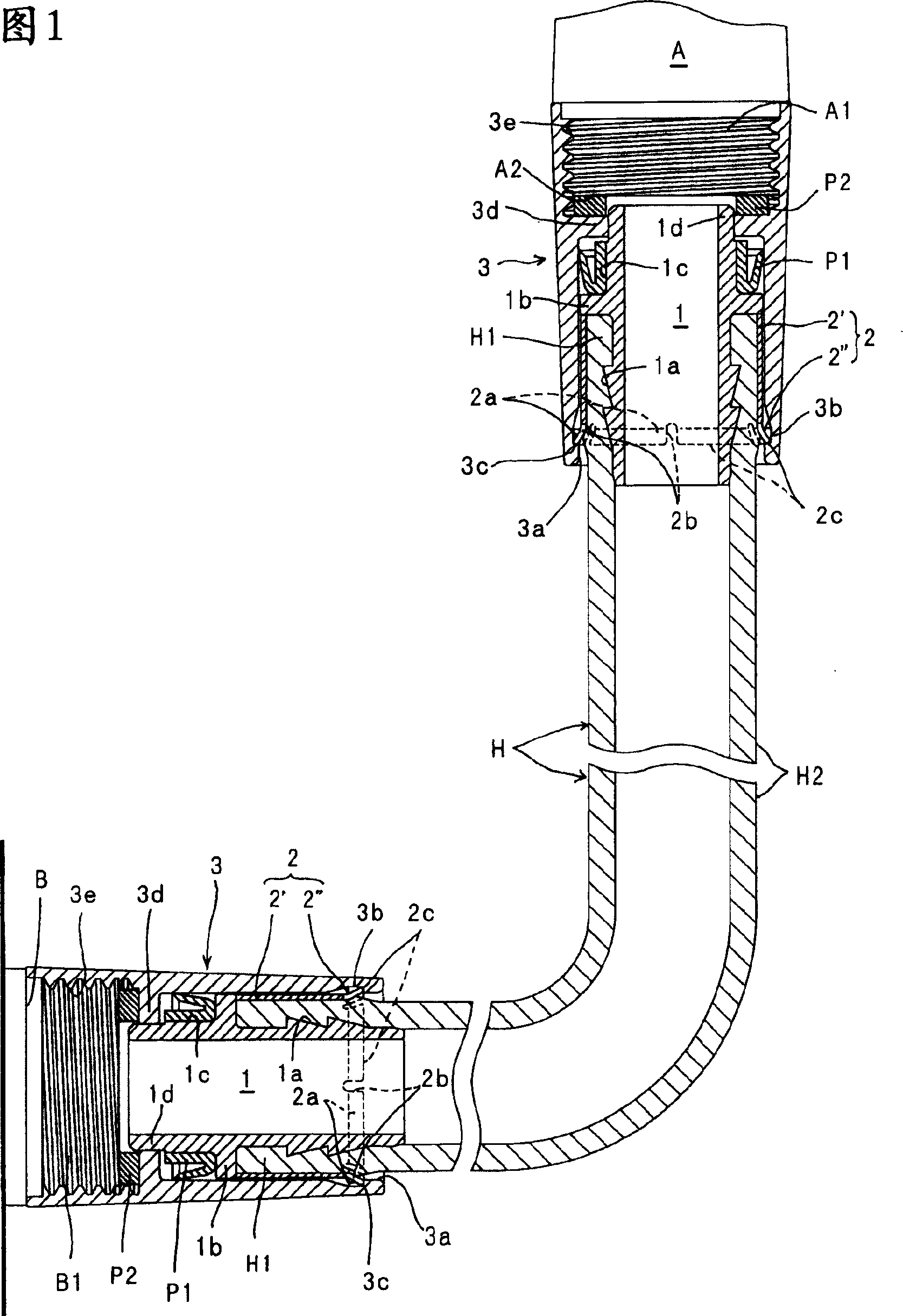
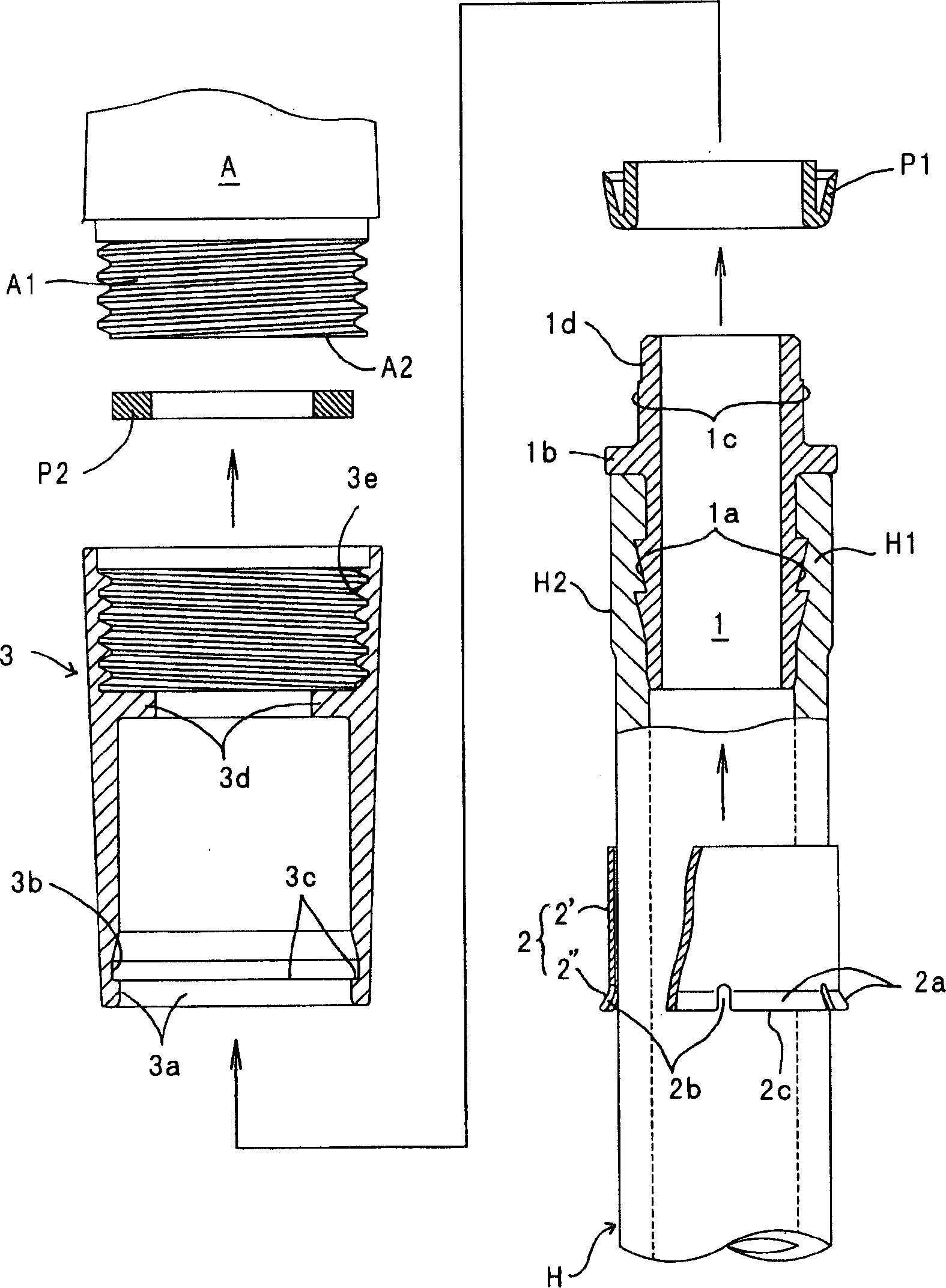
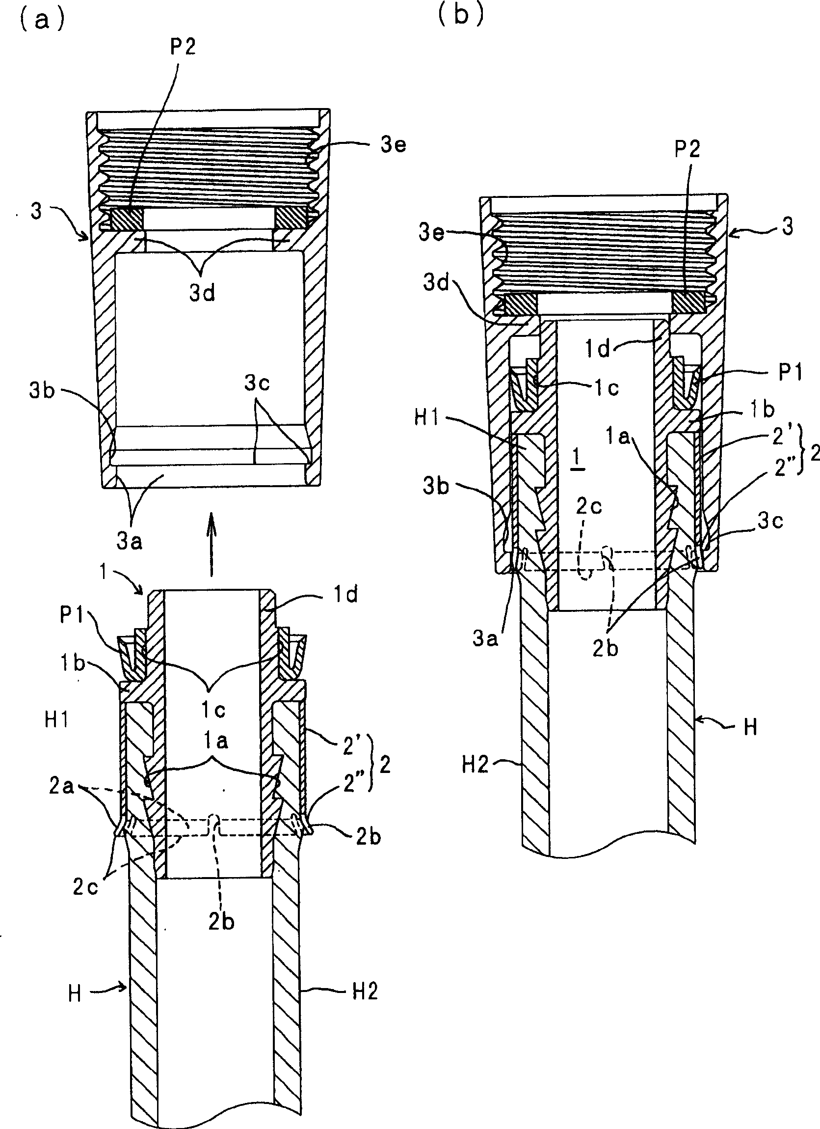
[0057] This embodiment 1 is shown in Fig. 1~ image 3 As shown, the above-mentioned pressure cylinder 2 is an integrally formed product in which the cylindrical part 2' and the elastic joint part 2" are continuously formed in the axial direction, and the base end side of these cylindrical part 2' and the elastic joint part 2" is integrally formed. Expanded diameter part 2a.
[0058] In the example shown in the figure, such as figure 2 As shown, a plurality (six) of space portions 2 b for diameter reduction are provided at equal intervals in the circumferential direction on the proximal edge 2 c of the diameter expansion portion 2 a.
[0059] In addition, by allowing the inner peripheral surface of the packing support protrusion 3d of the connecting cylinder 3 to be rotatably inserted through the outer peripheral surface of the joint portion 1d of the pipe joint 1 , the pipe joint 1 is prevented from moving against the connecting cylinder 3 . shaking.
[0060] Next, the conn...
Embodiment 2
[0070] The embodiment 2 as Figure 4 ~ Figure 5 As shown, the above-mentioned pressure cylinder 2 is an assembled molded part, and a cylindrical cylindrical part 2' and a substantially cylindrical elastic joint part 2" protruding from the cylindrical part only from the enlarged diameter part 2a are respectively formed. The outer side of the cylindrical part 2' is fixed so that the elastic joint part 2" cannot move in the axial direction, so that the elastic joint part 2" is arranged and fixed on the radially outer side of the cylindrical part 2'. image 3 The illustrated embodiment 1 is different, and the other configurations are the same as those shown in Figs. image 3 shown
[0071] Example 1 is the same.
[0072] As a method of manufacturing such a press cylinder 2, such as Figure 5 (a) As shown in (b), at first, only one of the two openings of the cylindrical part 2' is processed for diameter expansion, and the diameter expansion is formed in advance by inserting from...
Embodiment 3
[0078] The present embodiment 3 such as Figure 6 ~ Figure 7 As shown, the above-mentioned pressing cylinder 2 is an integral molded part in which the base end side of the cylindrical cylindrical part 2' is folded back and the elastic joint part 2" is arranged and fixed on the radially outer side of the cylindrical part 2'. With the above figure 1~ image 3 The illustrated embodiment 1 is different, and the other configurations are the same as those shown in Figs. image 3 Example 1 shown is the same.
[0079] As a method of manufacturing such a press cylinder 2, such as Figure 7As shown in (a) to (c), at first, for example, punch out the base end portion of the cylindrical portion 2′ by punching, etc., to form the slit-shaped diameter-reducing space portion 2b, and then turn the base end portion by folding back. The expanded diameter portion 2a of the elastic engagement portion 2" is integrally formed by being folded back along the outer peripheral surface of the cylindri...
PUM
 Abstract
Description
Claims
Application Information
 - R&D
- Intellectual Property
- Life Sciences
- Materials
- Tech Scout
- Unparalleled Data Quality
- Higher Quality Content
- 60% Fewer Hallucinations
Browse by: Latest US Patents, China's latest patents, Technical Efficacy Thesaurus, Application Domain, Technology Topic, Popular Technical Reports.
© 2025 PatSnap. All rights reserved.Legal|Privacy policy|Modern Slavery Act Transparency Statement|Sitemap|About US| Contact US: help@patsnap.com


