Refrigerant compressor

A compressor and refrigerant technology, applied in mechanical equipment, machinery/engine, liquid variable capacity machinery, etc., can solve the problems of increasing suction loss, reducing refrigeration capacity and refrigeration efficiency, etc.

Inactive Publication Date: 2005-11-16
PANASONIC CORP
View PDF1 Cites 6 Cited by
  • Summary
  • Abstract
  • Description
  • Claims
  • Application Information

AI Technical Summary

Problems solved by technology

Since in this case, increasing the elastic constant of the deformation part 67A, the bending amount of the deformation part 67A is reduced and the suction loss is increased, and the cooling capacity and cooling efficiency are reduced.

Method used


Image

  • Refrigerant compressor
  • Refrigerant compressor
  • Refrigerant compressor

Examples


Embodiment Construction

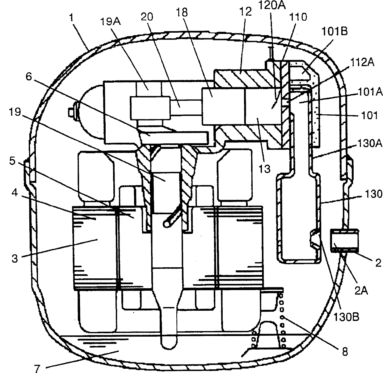
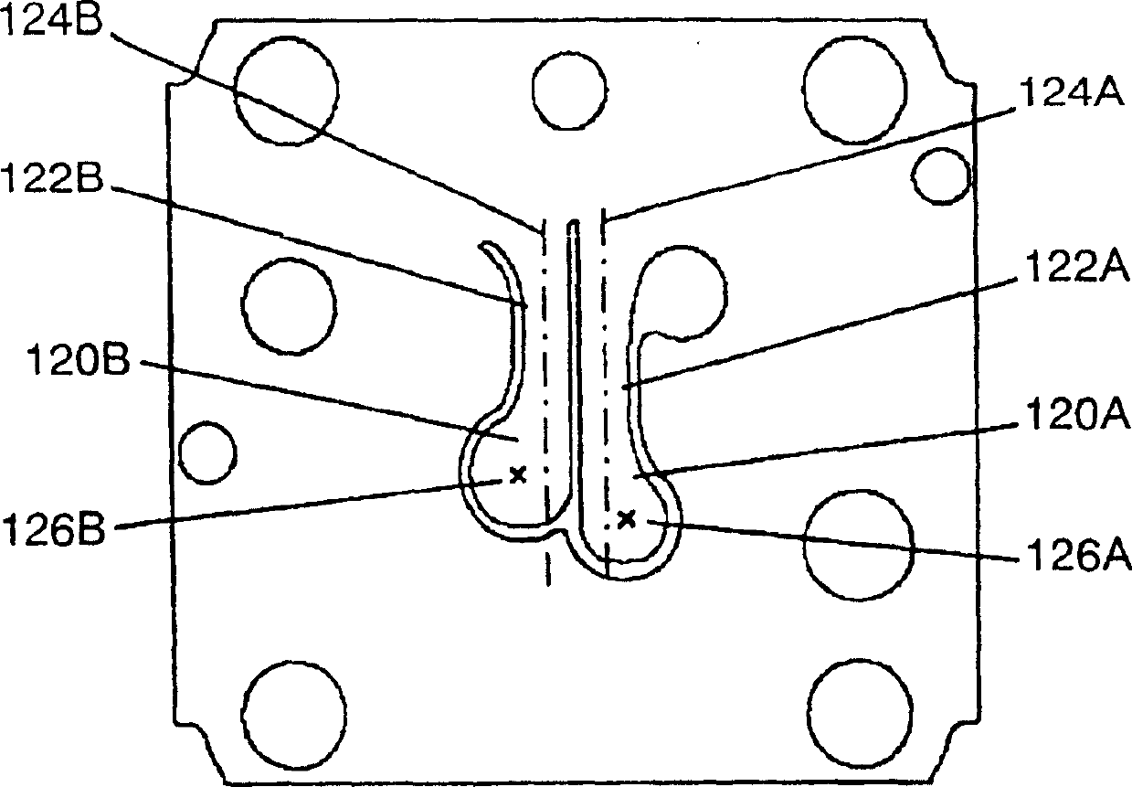
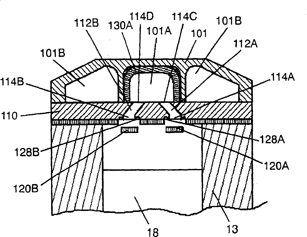
[0017] Fig. 1 is a cross-sectional view of a refrigerant compressor according to an embodiment of the present invention. Fig. 2 is a front view of the suction reed valve. Fig. 3 is a sectional view of a cylinder head.

[0018] One end of the suction pipe 2, that is, an outlet portion 2A, is connected to the airtight container 1, and the other end of the suction pipe 2 is connected to a low-pressure side pipe (not shown) of the refrigeration cycle. A motor 3 constituted by a stator 4 and a rotor 5 drives a compressor 6 . Furthermore, the refrigerating machine oil 7 is stored in the bottom of the airtight container 1 . The coil spring 8 elastically supports the motor 3 and the compression part 6 .

[0019] Compression unit 6 is constituted by cylinder head 101 , cylinder block 12 , valve plate 110 , suction reed valves (hereinafter referred to as valves) 120A, 120B, piston 18 , connecting rod 20 and suction muffler 130 . The cylinder head 101 is formed with an intake space 1...


PUM


Abstract

A valve plate includes a plurality of suction holes and a plurality of suction reed valves for opening and closing them. At least two of theses suction reed valves have different natural frequencies. In this configuration, a natural frequency of one reed valve is larger. Therefore, even when an operation frequency is changed to a higher frequency, the compressor can suck a refrigerant gas into a cylinder efficiently without occurring delayed closing and reduction of a lift amount. Thus, refrigerating capacity and compression efficiency can be increased.

Description

technical field [0001] The present invention relates to an improvement in the efficiency of a hermetic compressor used in a freezer or the like. Background technique [0002] In recent years, there has been a strong desire to improve the efficiency of hermetic compressors used in freezers and the like. In conventional hermetic compressors, for example, the compression efficiency is improved by increasing the suction efficiency by using two suction holes of the valve device of the compression section. Such a compressor is described, for example, in JP-A-3-175174. An example of a conventional compressor will be described below with reference to the drawings. [0003] FIG. 6 is a cross-sectional view of a conventional refrigerant compressor, and FIG. 7 is an exploded perspective view of a valve of a conventional refrigerant compressor. One end of the suction pipe 52 , that is, an outlet portion 52A, is connected to the airtight container 51 , and the other end of the suction...

Claims


Application Information

Patent Timeline
Patent Type & Authority Applications(China)
IPC IPC(8): F04B39/10
Inventor 小林正则
Owner PANASONIC CORP
Why Eureka
Try Eureka