A Common Rail Injector with Reduced Leakage

A technology of common rail injectors and oil chambers, applied in fuel injection devices, machines/engines, charging systems, etc., which can solve problems such as power loss, efficiency decline, and fuel system economy reduction in common rail systems

Active Publication Date: 2020-07-17
CHINA FIRST AUTOMOBILE
View PDF4 Cites 0 Cited by
  • Summary
  • Abstract
  • Description
  • Claims
  • Application Information

AI Technical Summary

Problems solved by technology

With the increase of the fuel injection pressure of the common rail system, the leakage of the fuel injector will increase significantly, which will cause the power loss of the common rail system to be obvious, the efficiency will decrease, and the economy of the fuel system will be reduced
At the same time, more high-pressure fuel leaks into the low-pressure oil circuit, which will lead to a higher temperature of the low-pressure oil circuit in the injector, which will affect the stability and reliability of the injector, making it difficult to increase the injection pressure.

Method used


Image

  • A Common Rail Injector with Reduced Leakage
  • A Common Rail Injector with Reduced Leakage
  • A Common Rail Injector with Reduced Leakage

Examples


Embodiment Construction

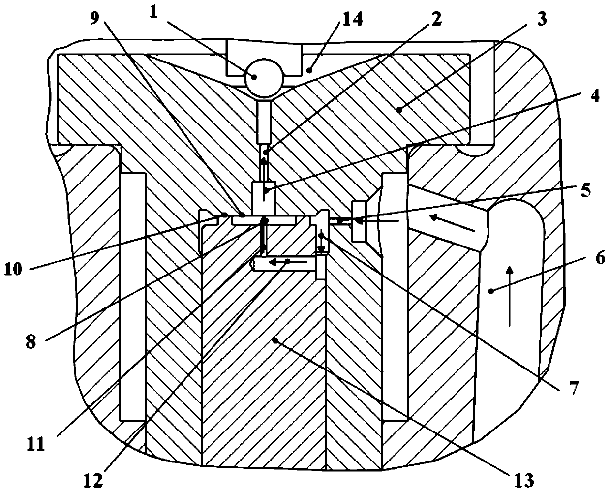
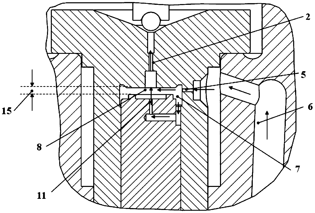
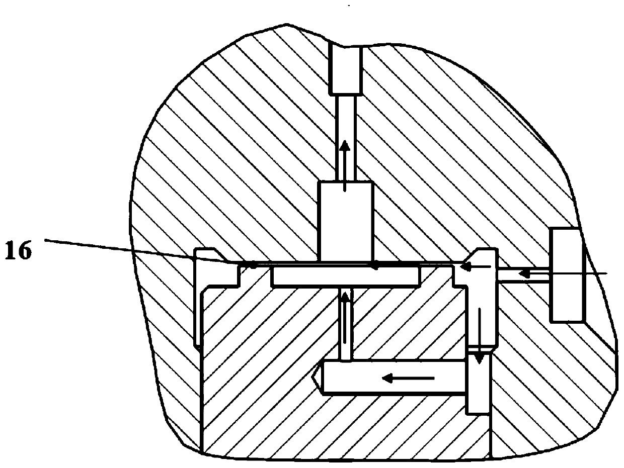
[0020] A common rail fuel injector that reduces leakage in the present invention can refer to the attached figure 1 , 2 , 3 descriptions.

[0021] A common rail fuel injector that reduces leakage, including a ball valve 1, an orifice 3, and a control piston 13. During fuel injection, after the control piston 13 rises, a seal is formed between the bottom of the orifice 3 and the control piston 13 Annulus 16, an oil chamber A8 and an oil chamber B7 are formed between the top of the control piston 13 and the bottom of the orifice plate 3, and the oil chamber A8 and oil chamber B7 are respectively located inside and outside of the throttle annulus 16 and located at the control On the top of the piston 13, two oil chambers form the injector control chamber; the oil chamber A8 is controlled by the ball valve 1 to communicate with the low-pressure oil passage 14 through the oil outlet hole 2 on the orifice plate 3; the oil chamber B7 passes through The oil inlet hole 5 is connected...


PUM


Abstract

The invention provides a common rail oil injector capable of reducing leakage. The common rail oil injector comprises an oil cavity A and an oil cavity B, wherein the oil cavity A and the oil cavity Bare formed by a control piston and a pore plate; when the control piston ascends and descends, a high-pressure oil passage communicates with a low-pressure oil passage through two oil passages of theoil cavity A and the oil cavity B. After the lift of the control piston reaches the maximum value, the communication between the oil cavity B and the low-pressure oil passage through a throttling ring belt is cut off, high-pressure oil only passes through a throttling hole and the oil cavity A to be leaked to the low-pressure oil passage through an oil outlet hole, so that the flowing resistanceis increased, and oil return during oil spraying, heating of the oil injector and oil supply pump power loss are reduced. Meanwhile, the flow ratio of the oil outlet hole to an oil inlet hole can be larger, so that the oil drainage time of a control cavity and the oil injection delay of the oil injector are reduced. After the communication of a passage, flowing through the throttling ring belt, between the oil cavity B and the low-pressure oil passage is cut off, and the oil cavity B only communicates with the low-pressure oil passage through the throttling hole and the oil cavity A, so that the flowing resistance of the low-pressure oil passage is increased, and the oil cavity B is kept higher in pressure, the pressure of the control cavity is restored faster after an electromagnetic valve is powered off, the oil spraying closing delay is shorter, and the oil spraying sensitivity of the oil injector is improved.

Description

technical field [0001] The invention belongs to the field of fuel injection systems of internal combustion engines, and in particular relates to a common rail fuel injector for reducing leakage. Background technique [0002] According to the working principle of the common rail injector, the injector controls the rise or fall of the fuel pressure in the control chamber, so that the control piston of the fuel injector can move up and down in the axial direction through the pressure difference. Similar fuel injectors are disclosed in CN101548092A, CN102282354A, CN201210199068.8, and CN200820014041.6. During the fuel injection process, both the inlet and outlet orifices are open, and the high-pressure fuel will flow back to the fuel tank through the inlet and outlet orifices. As the fuel injection pressure of the common rail system increases, the leakage of the fuel injector will increase significantly, resulting in significant power loss of the common rail system, a decrease ...

Claims


Application Information

Patent Timeline
Patent Type & Authority Patents(China)
IPC IPC(8): F02M61/16
CPCF02M61/16
Inventor 郭立新居钰生杨海涛施东晓徐世龙李康宁
Owner CHINA FIRST AUTOMOBILE
Why Eureka
Try Eureka