
Display device

A technology of display device and capacitive line, which can be used in identification devices, static indicators, optics, etc., and can solve problems such as complex driving methods

Inactive Publication Date: 2005-11-23
SANYO ELECTRIC CO LTD
View PDF1 Cites 2 Cited by
  • Summary
  • Abstract
  • Description
  • Claims
  • Application Information

AI Technical Summary

Problems solved by technology

However, this method has the problem that the driving method tends to be complicated

Method used


Image

  • Display device
  • Display device
  • Display device

Examples


Embodiment Construction

[0060] Embodiments of the present invention will be described below with reference to the drawings.

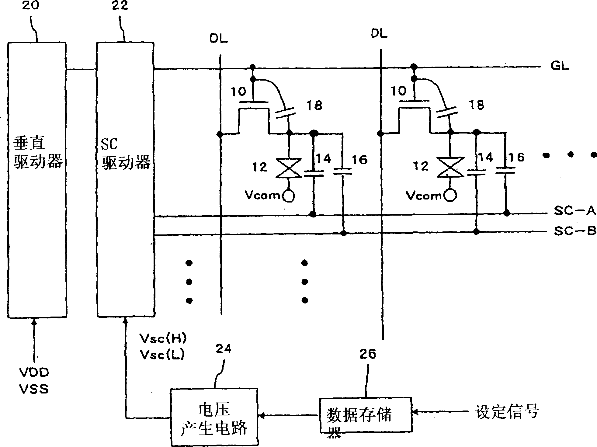
[0061] figure 1 The schematic structure of this embodiment is shown. The pixel circuits 1 are arranged in a matrix in the entire display area. The matrix configuration can also be zigzag rather than a complete grid. In addition, the display can be black and white, or full color (full color). When it is full color, the pixels are generally RGB three colors, but pixels of a specific color including white can also be added as needed.

[0062]As shown in the figure, one pixel circuit 1 has: an n-channel pixel TFT (thin film transistor, thin film transistor) 10 whose drain is connected to the data line DL; a liquid crystal component 12 connected to the source of the pixel TFT 10; and holding Capacitor 14. The gates of the pixel TFTs 10 are connected to gate lines GL arranged for every horizontal scanning line. Here, a gate capacitance 18 is always generated between the gate an...


PUM


Abstract

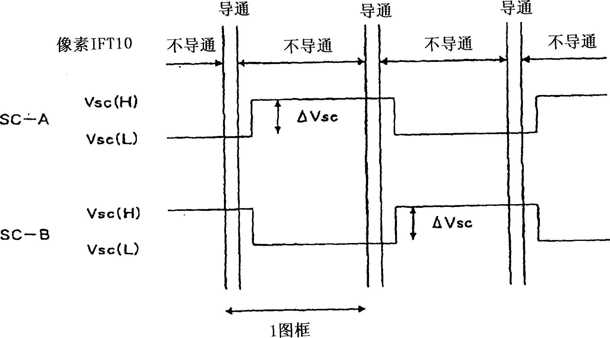
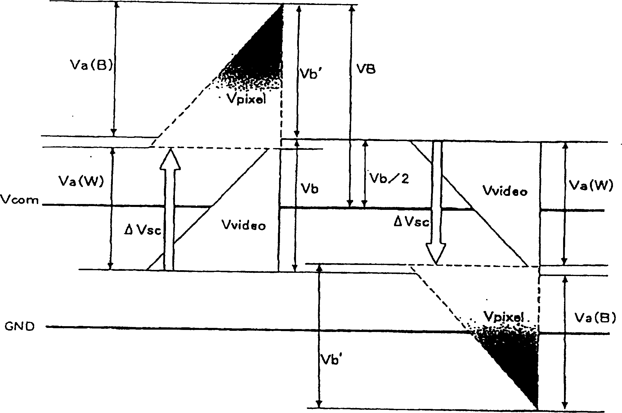
The level of a storage capacitor line is changed between two types, an H level and an L level. As a result of this change, the voltage applied to a liquid crystal is shifted so that a sufficient voltage is applied to the liquid crystal to perform a display operation. Then, at least one of two voltage levels of the storage capacitor line is used in common with the potential of at least one of plurality of voltage levels which are used in vertical driver which drives the said selection line. Furthermore, the values of the storage capacitance and parasitic capacitance for the storage capacitor line are set within a specific range.

Description

technical field [0001] The present invention relates to a display device in which pixel circuits are arranged in a matrix. Background technique [0002] Conventionally, liquid crystal display devices have been known as thinner and smaller display devices with low power consumption, and have been adopted as displays for various devices. This liquid crystal display device (hereinafter referred to as LCD (Liquid Crystal Display)) has a configuration in which liquid crystal is sealed and bonded between two substrates each having electrodes formed on opposite sides. Furthermore, a voltage signal is applied between the electrodes to control the alignment of the liquid crystal whose optical properties are changed according to the alignment state, and further control the transmittance of light from the light source, thereby performing display. [0003] Here, when a DC voltage is continuously applied between the electrodes formed on the facing side of the substrate, it is known that...

Claims


Application Information

Patent Timeline
Patent Type & Authority Applications(China)
IPC IPC(8): G02F1/136G09G3/36
Inventor 千田满广泽浩司横山良
Owner SANYO ELECTRIC CO LTD
Learn More