
Micro adhesive nozzle and adhesive applying apparatus

A technology for adhesives and nozzles, applied in the field of adhesive nozzles, which can solve the problem of touching the top of the nozzle

Inactive Publication Date: 2005-11-30
RICOH KK
View PDF4 Cites 2 Cited by
  • Summary
  • Abstract
  • Description
  • Claims
  • Application Information

AI Technical Summary

Problems solved by technology

[0009] However, according to the technique proposed above, when the interval between adjacent chip components is narrow, the applied adhesive may contact the adjacent chip components, and it may also contact the top of the nozzle. , so the nozzle needs to be cleaned afterwards

Method used


Image

  • Micro adhesive nozzle and adhesive applying apparatus
  • Micro adhesive nozzle and adhesive applying apparatus
  • Micro adhesive nozzle and adhesive applying apparatus

Examples


Embodiment Construction

[0030] Hereinafter, preferred embodiments of the present invention will be described with reference to the accompanying drawings.

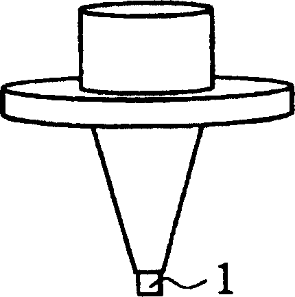
[0031] FIG. 9 shows the structure of an adhesive applying device including a miniature adhesive nozzle according to an embodiment of the present invention.

[0032] The adhesive applying device in FIG. 9 includes a printed circuit board 21 , a head unit 28 , a table unit 35 , and guides 37 and 38 . The head unit 28 can be guided by the guide 37 to move in the X direction (represented by the double-headed arrow X-X in FIG. Y-Y means) move. The head unit 28 comprises an adhesive application head 45 and a damping unit 47 , wherein the adhesive application head 45 is realized by the adhesive nozzle 26 with the nozzle top 29 . The printed circuit board 21 is supported by the table unit 35 via support pins 36 . By moving the head unit 28 in the X direction and the table unit 35 in the Y direction, the adhesive nozzle 26 can be positioned at a desired...


PUM

PropertyMeasurementUnit
Heightaaaaaaaaaa

Abstract

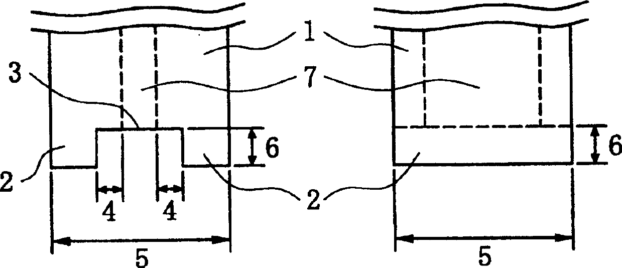
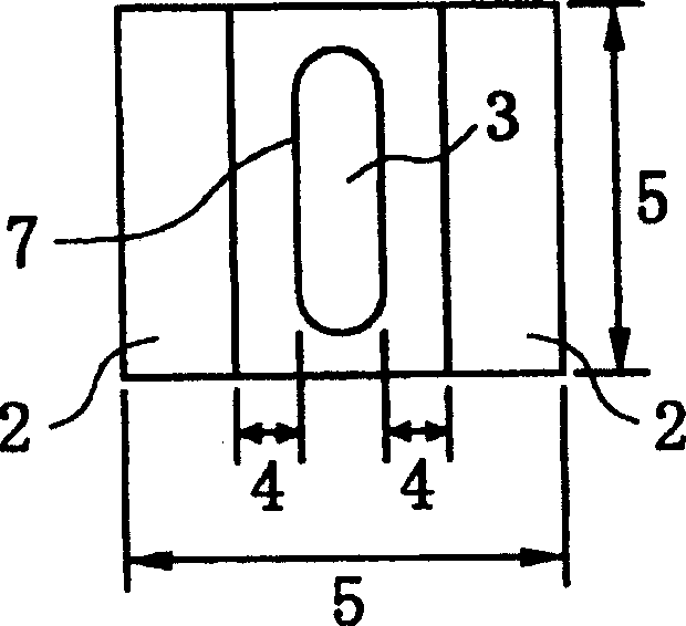
A micro adhesive nozzle for applying adhesive on a printed circuit board is disclosed. The nozzle includes a nozzle tip portion with a protruding portion arranged at a periphery of the nozzle tip portion, an adhesive discharge opening portion formed within the periphery of the nozzle tip portion, and a gap provided between the discharge opening portion and the protruding portion.

Description

technical field [0001] The present invention generally relates to a miniature adhesive nozzle for applying adhesive to a printed circuit board, and an adhesive applicator having such a nozzle. In particular, the present invention relates to an adhesive nozzle which enables stable application of adhesive for bonding micro components such as chip components, and which also prevents the amount of applied adhesive from varying, The adhesive applying nozzle is also arranged so that the tip of the nozzle does not come into contact with the adhesive even when the interval between the chip components to be mounted is narrow. Background technique [0002] Typically, a mass soldering process is performed in a flow soldering bath during the process of soldering chip components and inserting the components into a printed circuit board. In performing the soldering process, in order to prevent the mounted chip components from coming off even when the chip components are placed on the bot...

Claims


Application Information

Patent Timeline
IPC IPC(8): B05C5/02
Inventor 小野正晴
Owner RICOH KK
Learn More