
A temperature-controllable cryogenic laser shock peening system

A laser shock strengthening and cryogenic technology, applied in the field of cryogenic treatment and laser processing, can solve the problems of low beam transmittance and low air heat transfer efficiency, so as to improve the cooling efficiency, reduce the heat transmission and the loss of liquid nitrogen. , the effect of simple structure

Active Publication Date: 2018-12-14
JIANGSU UNIV
View PDF4 Cites 0 Cited by
  • Summary
  • Abstract
  • Description
  • Claims
  • Application Information

AI Technical Summary

Problems solved by technology

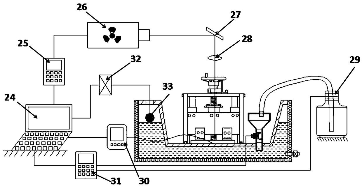
[0006] In view of the above problems, the purpose of the present invention is to provide a temperature-controllable cryogenic laser shock peening system, which maintains contact with liquid nitrogen through the embedded cryogenic box cover, and ensures that the workpiece is placed in a cryogenic environment by means of heat conduction. The thermometer monitors the temperature of the workpiece in real time, controls the height of the liquid nitrogen liquid level through the liquid level detection device and the liquid nitrogen automatic replenishment device, and then controls the contact area between the cryogenic box cover and the liquid nitrogen, thereby ensuring that the heat transfer to the workpiece makes it in different cryogenic temperatures temperature, and the workpiece is tightened by the screw platen to ensure the confinement effect, which solves the problem of low beam transmittance or low heat transfer efficiency with air due to the liquid nitrogen vaporized substance produced by the contact between the workpiece and liquid nitrogen during the cryogenic laser shock process , to achieve the experimental effect of cryogenic laser shock strengthening with controllable temperature and better confinement effect

Method used


Image

  • A temperature-controllable cryogenic laser shock peening system
  • A temperature-controllable cryogenic laser shock peening system
  • A temperature-controllable cryogenic laser shock peening system

Examples


Embodiment Construction

[0030] The present invention will be further described below in conjunction with the accompanying drawings and specific embodiments, but the protection scope of the present invention is not limited thereto.

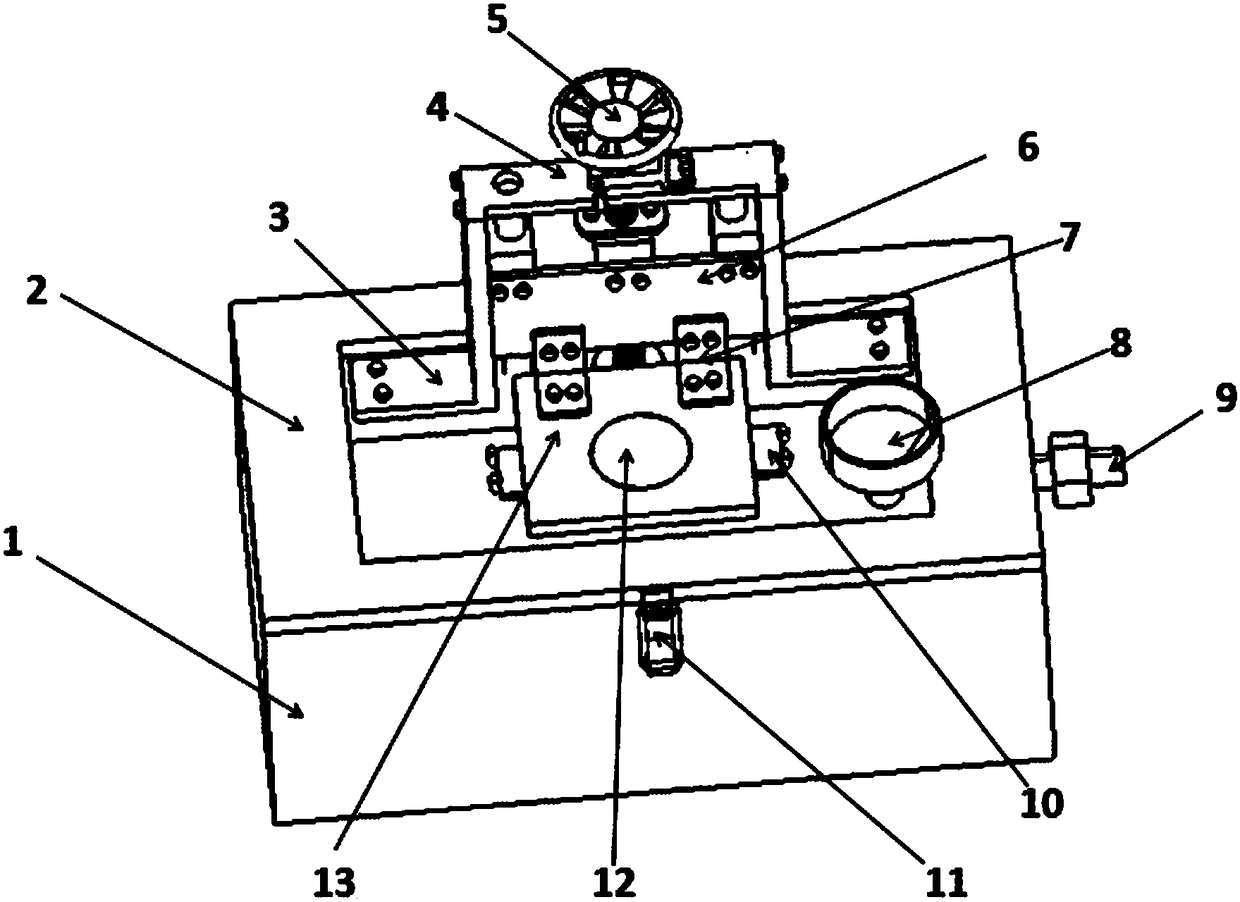
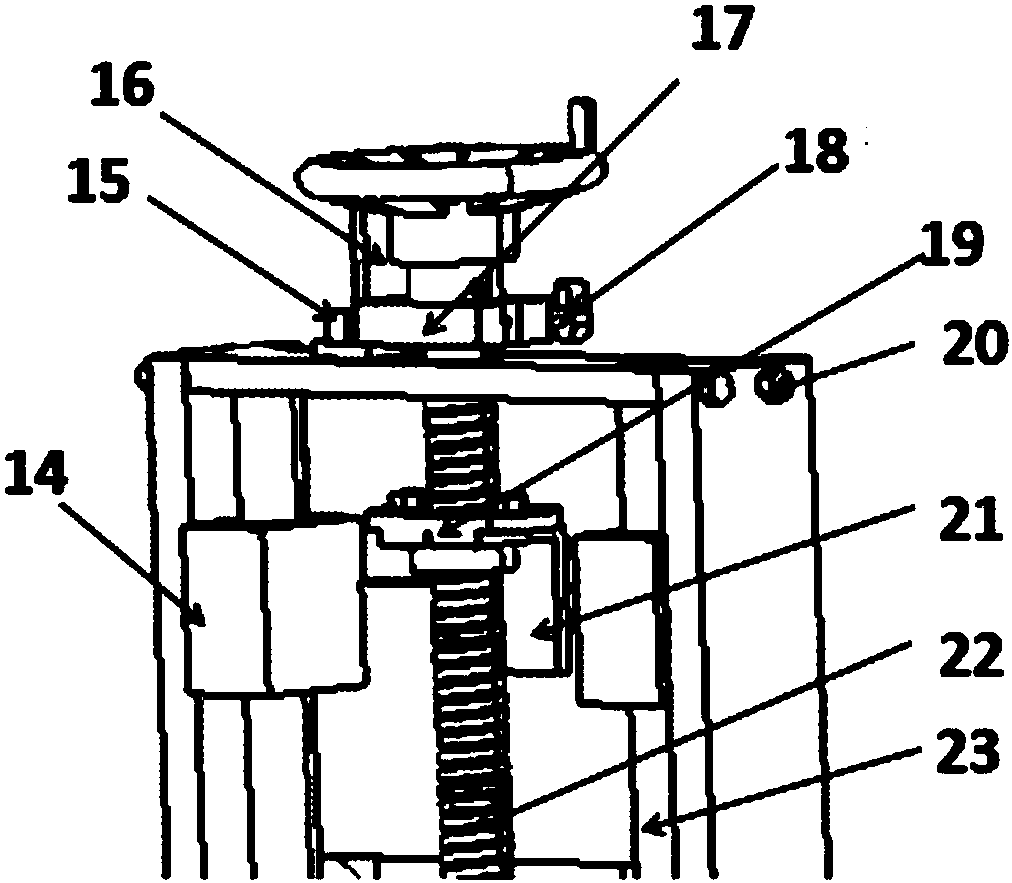
[0031] Such as figure 1 and figure 2 As shown, the clamping device in the temperature-controllable cryogenic laser shock peening system of the present invention includes a clamp base 2, a first support plate 3, a cover plate 4, a screw pressing device and a circumferential positioning device; two The first support plate 3 is fixed on the fixture base 2 by screwing, and the cover plate 4 is fixed between the two first support plates 3 and located on the top of the first support plate 3 . A cryogenic box cover can be used as the clamp base 2, and the cryogenic box cover is fixed on the cryogenic box body 1 by a buckle. The cover of the cryogenic box is provided with a funnel 8 communicating with the cryogenic box 1, and the cryogenic box 1 is provided with a pressure rel...


PUM


Abstract

The invention provides a temperature-controllable deep cooling laser shock peening system which comprises a clamp base, a liquid nitrogen automatic supplementary device, a liquid level monitor device, first supporting plates, a cover plate, a screw pressing device and a circumferential locating device. An automatic flow adjusting funnel, an electric liquid nitrogen pump, a liquid level monitor and a computer system are connected, it is guaranteed that the liquid nitrogen liquid level height is kept constant, and then the workpiece temperature is controllable; a screw pressing mechanism is used for tightening and locating a workpiece and a restraint layer; and the circumferential locating device achieves circumferential restraining on a screw through a clamping block and a check block. The clamping and locating process is fast and simple, the repeated locating precision is high, and locating is reliable; and the deep cooling laser shock peening experimental effects of being controllable in temperature and better in restraint effect are achieved.

Description

technical field [0001] The invention relates to the fields of cryogenic treatment and laser processing, in particular to a temperature-controllable cryogenic laser shock strengthening system. Background technique [0002] At present, laser shock strengthening technology has been successfully applied in aerospace, shipbuilding and automobile industries, and the emergence of laser shock strengthening technology has solved the defects of contact processing and long processing time of traditional metal material strengthening technology, but the current laser The impact strengthening technology is carried out at room temperature or high temperature. There is a contradiction between the strength and plasticity of the metal material obtained after strengthening. Although the laser shock strengthening technology at room temperature can improve the material strength, it will be accompanied by The plasticity is reduced, so that it cannot meet the requirements of aerospace titanium all...

Claims


Application Information

Patent Timeline
Patent Type & Authority Patents(China)
IPC IPC(8): C21D10/00
CPCC21D10/005
Inventor 周建忠孙云辉黄舒孟宪凯李京徐苏强徐洋洋
Owner JIANGSU UNIV
Learn More