
Thrust surface friction diminishing device for vane type compressor

A friction-reducing, vane-type technology used in parts of pumping devices for elastic fluids, rotary-piston/oscillating-piston pump parts, machinery, etc. to address performance degradation, oil shortage, compressor pressure problems such as rise, to achieve the effect of improving performance, improving reliability, and preventing pressure rise

Inactive Publication Date: 2005-12-07
LG ELECTRONICS (TIANJIN) APPLIANCES CO LTD
View PDF0 Cites 3 Cited by
  • Summary
  • Abstract
  • Description
  • Claims
  • Application Information

AI Technical Summary

Problems solved by technology

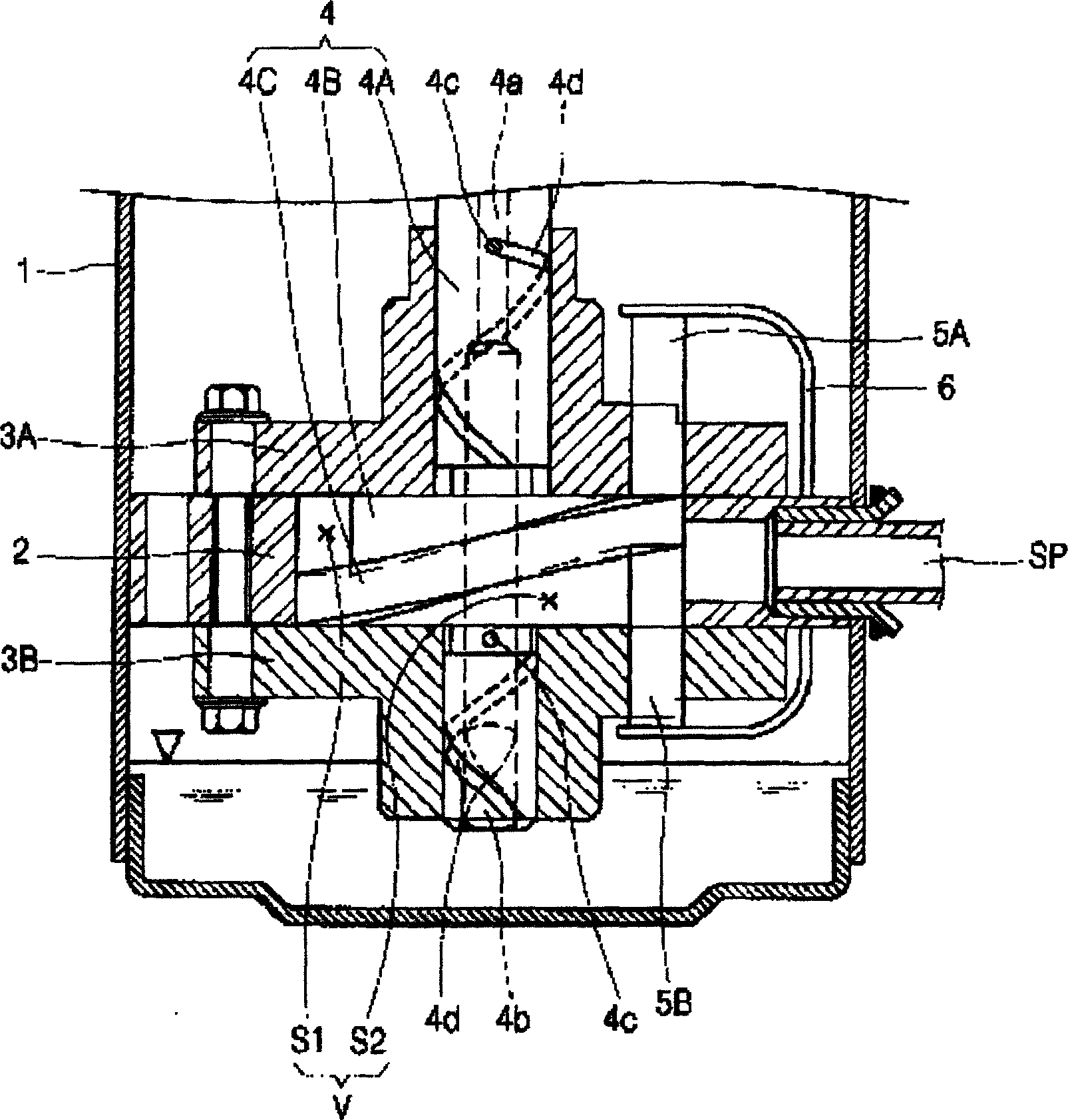
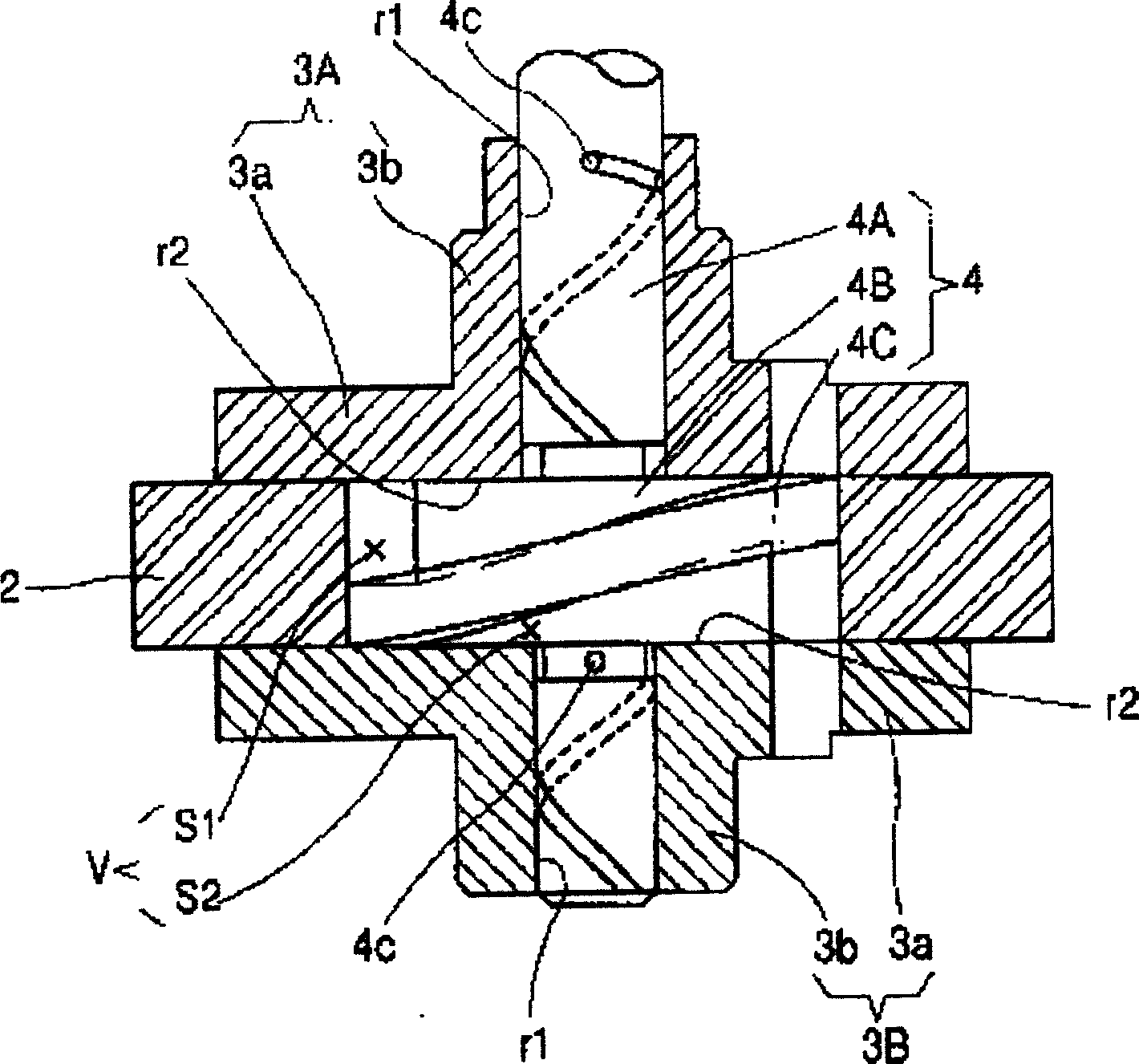
[0015] However, in the prior art vane compressor, the thrust surface of the second bearing plate 3B is the lower thrust surface r2, and the lower thrust bearing portion of the rotating shaft 4 and the lower thrust surface r2 rotate Axial and axial support, the lower thrust surface r2 receives more load than the upper thrust surface r2, and the lower thrust surface r2 forms an oil hole 4c around the compression space, and the oil hole 4c is at the center of the rotating shaft In the middle, it can only be on the periphery of the first bearing plate 3A and the lower part of the lower thrust surface r2, so the lower thrust surface r2 will suffer from a particularly serious oil shortage, and the pressure of the compressor may increase and the performance will decrease.

Method used


Image

  • Thrust surface friction diminishing device for vane type compressor
  • Thrust surface friction diminishing device for vane type compressor
  • Thrust surface friction diminishing device for vane type compressor

Examples


Embodiment Construction

[0039] The thrust surface friction reduction device of the vane compressor of the present invention will be further described in detail in conjunction with the accompanying drawings and specific embodiments:

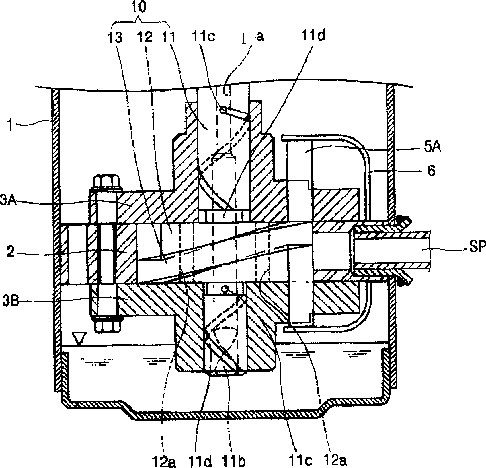
[0040] Such as Figure 3 to Figure 5 As shown, the compression mechanism of the vane compressor of the present invention includes a cylinder 2, a first bearing plate 3A and a second bearing plate 3B, a first bearing plate 3A and a second bearing plate 3B, a rotating shaft 10, and a first blade 5A. And the second blade 5B, blade spring 6, the cylinder 2 includes the internal space V for sucking compressed refrigerant gas, and is fixed on the lower half of the shell 1, and the first bearing plate 3A and the second bearing plate 3B are respectively installed on the cylinder 2 and the bottom, together form the cylinder assembly, the rotating shaft 10 divides the internal space V of the cylinder assembly into a plurality of closed spaces, the rotating shaft 10 also includes a...


PUM


Abstract

This invention relates to a thrust surface friction reducing device of vane-type compressor. The vane-type compressor comprises cylinder, rotating shaft, several shaft bearing plates, several blades, wherein the cylinder has an inner space with upper and lower openings, and the several shaft bearing plates are connected with the openings separately; the rotating shaft comprises axle, bearing part and wiper part, wherein the axle is go through the shaft bearing plate, and inside the axle it forms oil channel; the bearing part is axially supported by the shaft bearing plate, the wiper part is formed in the outer surface of the bearing part; several blades press in the upper and lower laterals of the wiper part, changing the inner space to sucking area and compressing area; the bearing part forms oil channel axially, the oil will be sucked by the oil channel of the rotating shaft, one part of which will be guided to the lower thrust surface with the largest load.

Description

technical field [0001] The invention relates to the field of a thrust surface friction reduction device of a vane compressor, in particular to a thrust surface friction reduction device of a vane compressor that reduces the friction loss on the thrust surface of a rotating shaft and a corresponding bearing plate. Background technique [0002] The vane compressor in the prior art has blades on the rotating body, which divides the inner space of the cylinder into a suction area and a compression area, and the rotating body continuously switches between the suction area and the compression area, so that the fluid is sucked, compressed, and discharged. [0003] Such as figure 1 As shown, the vane compressor in the prior art is composed of a motor mechanism part and a compression mechanism part. The motor mechanism part is on the inner upper part of the shell 1 and generates power. The compression mechanism part is connected to the motor mechanism part and sucks, compresses and d...

Claims


Application Information

Patent Timeline
Patent Type & Authority Applications(China)
IPC IPC(8): F04C29/02
Inventor 金荣宗
Owner LG ELECTRONICS (TIANJIN) APPLIANCES CO LTD
Learn More