Punching apparatus

A punching device and punching die technology, applied in the field of punching device, can solve problems such as difficulty, raw material rupture, cost increase, etc., and achieve the effects of suppressing excessive inflow, preventing rupture, and reducing deformation

A punching device and punching die technology, applied in the field of punching device, can solve problems such as difficulty, raw material rupture, cost increase, etc., and achieve the effects of suppressing excessive inflow, preventing rupture, and reducing deformation

CN1706572AInactive Publication Date: 2005-12-14KUCHO GIKEN IND

Image

  • Punching apparatus
  • Punching apparatus
  • Punching apparatus

Examples


no. 1 approach

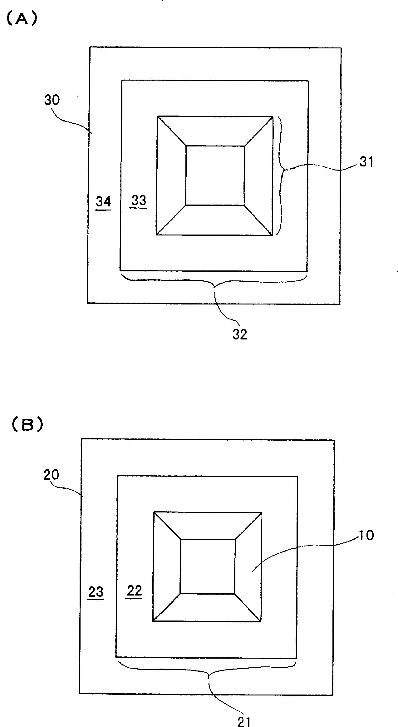
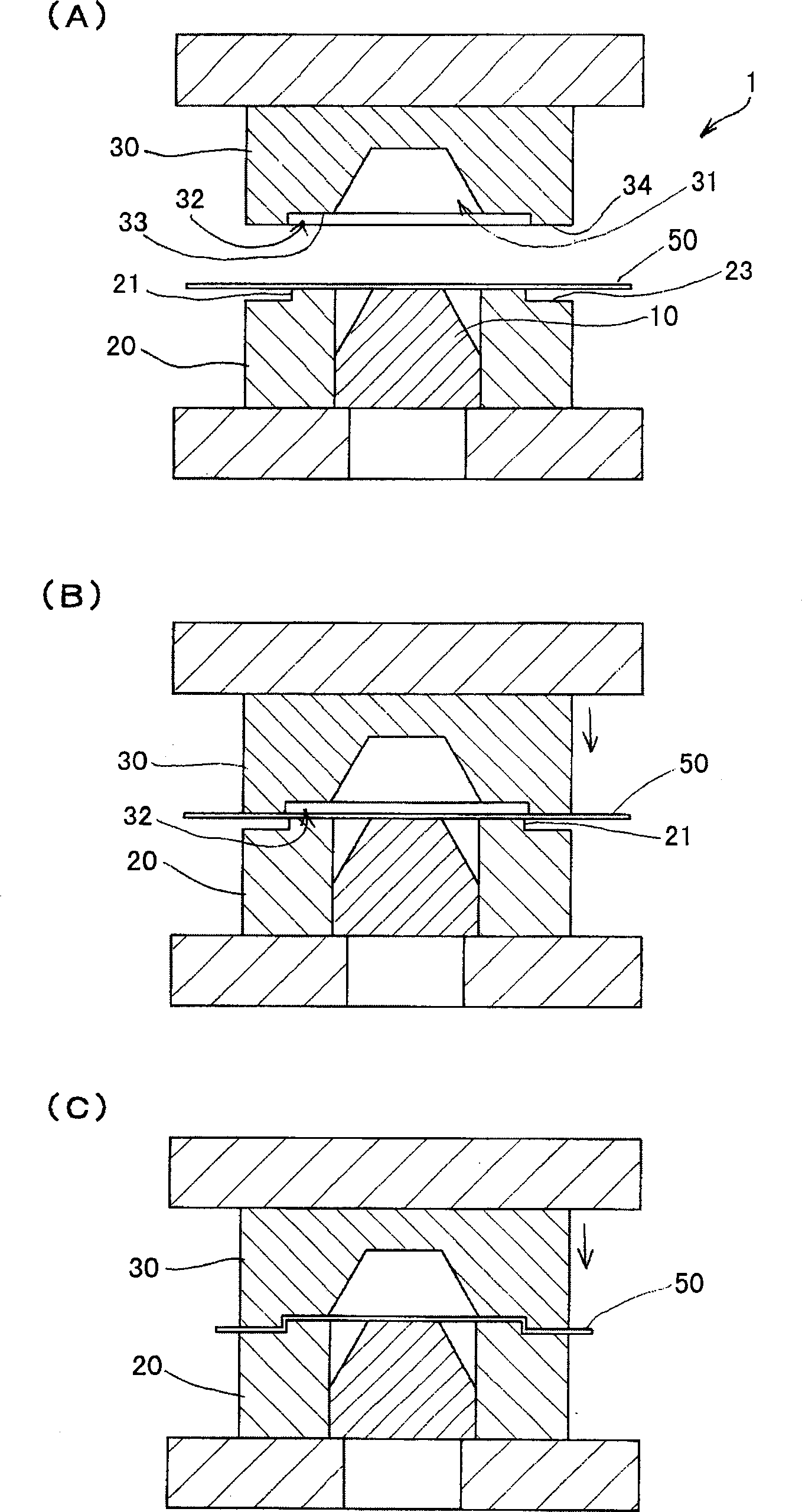
[0034] Below, according to Figure 1 to Figure 3 A first embodiment of the present invention will be described. figure 1 It is a bottom view of a die part and a top view of a punch part and a jig part of a die constituting a press device according to the present embodiment, figure 2 It is an explanatory diagram of the workpiece holding process of the press device related to the present embodiment. image 3 It is an explanatory diagram of a process of forming a workpiece by the press device according to the present embodiment.

[0035] The punching device related to this embodiment shown in the above-mentioned figures has a pair of metal molds 1 facing up and down, and the workpiece 50 made of a metal sheet that is put in and taken out between the upper and lower metal molds is made of metal. Die 1 is deep-drawn to form a square cone-shaped part for the exhaust port device. Each part of the press device other than the die 1 is a well-known structure, and its description is om...

no. 2 approach

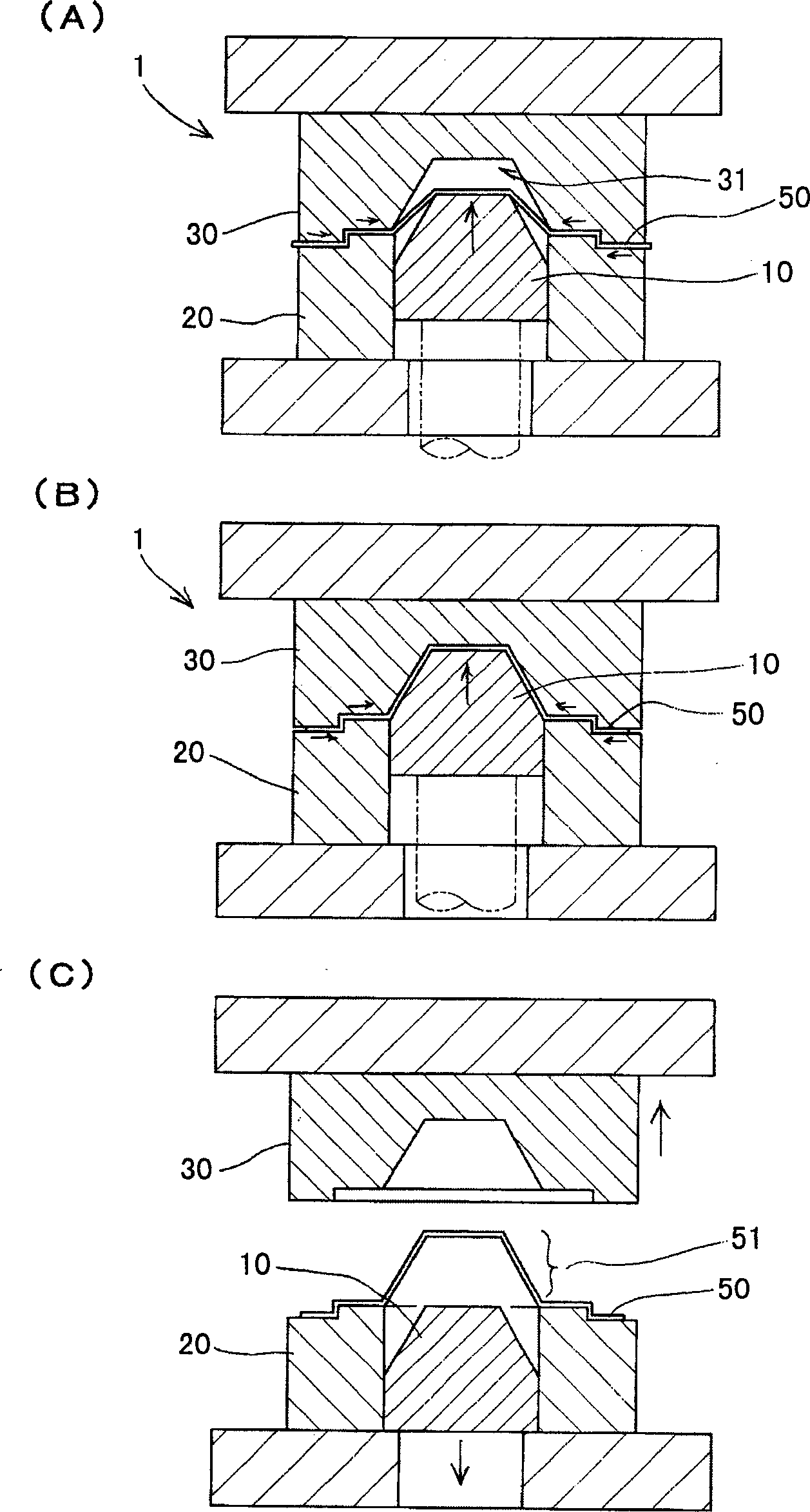
[0049] according to Figure 4 to Figure 6 A second embodiment of the present invention will be described. Figure 4 It is a bottom view of a die part of a die constituting a press device according to a second embodiment of the present invention, and a plan view of a punch part and a jig part, Figure 5 It is an explanatory diagram of the workpiece holding process of the press device related to the second embodiment of the present invention, Figure 6 It is an explanatory diagram of a process of forming a workpiece by a press device related to the second embodiment of the present invention.

[0050] The press device related to this embodiment shown in the preceding figures has a pair of dies 1 as in the first embodiment, and the shape of the jig part 20 and the die part 30 constituting the die 1 is partially different. Structure. In addition, as in the above-mentioned first embodiment, each part of the press device other than the die 1 is a well-known mechanism, and descript...


PUM


Abstract

The punching device has punch head with proper outer shape and thus punches the punched material into square cone part with minimized tension difference and no crack in the punched material while the punch head deepens to form. The fixtureand the punch mold are provided with stepped part, so that after the machined material is fixed with the fixture and the punch mold, it may be formed in stepped shape. Force is applied to the machined material drawn to between the punch head and the punch mold to overcome the resistance for pass through the step, and this can control properly the amount of the machined the drawn to between the punch head and the punch mold, so as to suppress exceed entrance, equalize the tension in different parts of the machined material, reduce the deformation in various corner parts and inhibit crack likely produced in different corner parts.

Description

technical field [0001] The present invention relates to a press device for drawing and forming a conical member of an air-conditioning exhaust port device, and particularly relates to a press device capable of drawing and forming a material to be processed properly without cracking. Background technique [0002] In the exhaust port device for air conditioners, the multi-layer conical exhaust port device has an outer cone and a middle cone. Considering its strength and cost, such conical parts are generally formed by metal plates. In the multi-layer conical exhaust port device, when the bottom shape is a square or rectangular square cone, the existing manufacturing method of the conical part is to mold each of the four members of each inclined surface part, It is manufactured integrally by welding the end portions corresponding to the corner portions to each other. [0003] The manufacturing of the conventional square cone-shaped parts is carried out as described above, and ...

Claims


Application Information

Patent Timeline
14 Dec 2005
Publication
CN1706572A
IPC
B21D35/00
Inventors
近藤让二