Method of driving a non-volatile flip-flop circuit using variable resistor elements

A multivibrator, non-volatile technology, applied in circuits, electrical components, static memory, etc., can solve problems such as increasing current consumption

Inactive Publication Date: 2005-12-21
PANASONIC CORP
View PDF1 Cites 14 Cited by
  • Summary
  • Abstract
  • Description
  • Claims
  • Application Information

AI Technical Summary

Problems solved by technology

In addition, in normal operation, since the current used to fix the board line at Vdd / 2 is necessary, the current consumption is increased.

Method used


Image

  • Method of driving a non-volatile flip-flop circuit using variable resistor elements
  • Method of driving a non-volatile flip-flop circuit using variable resistor elements
  • Method of driving a non-volatile flip-flop circuit using variable resistor elements

Examples


Embodiment Construction

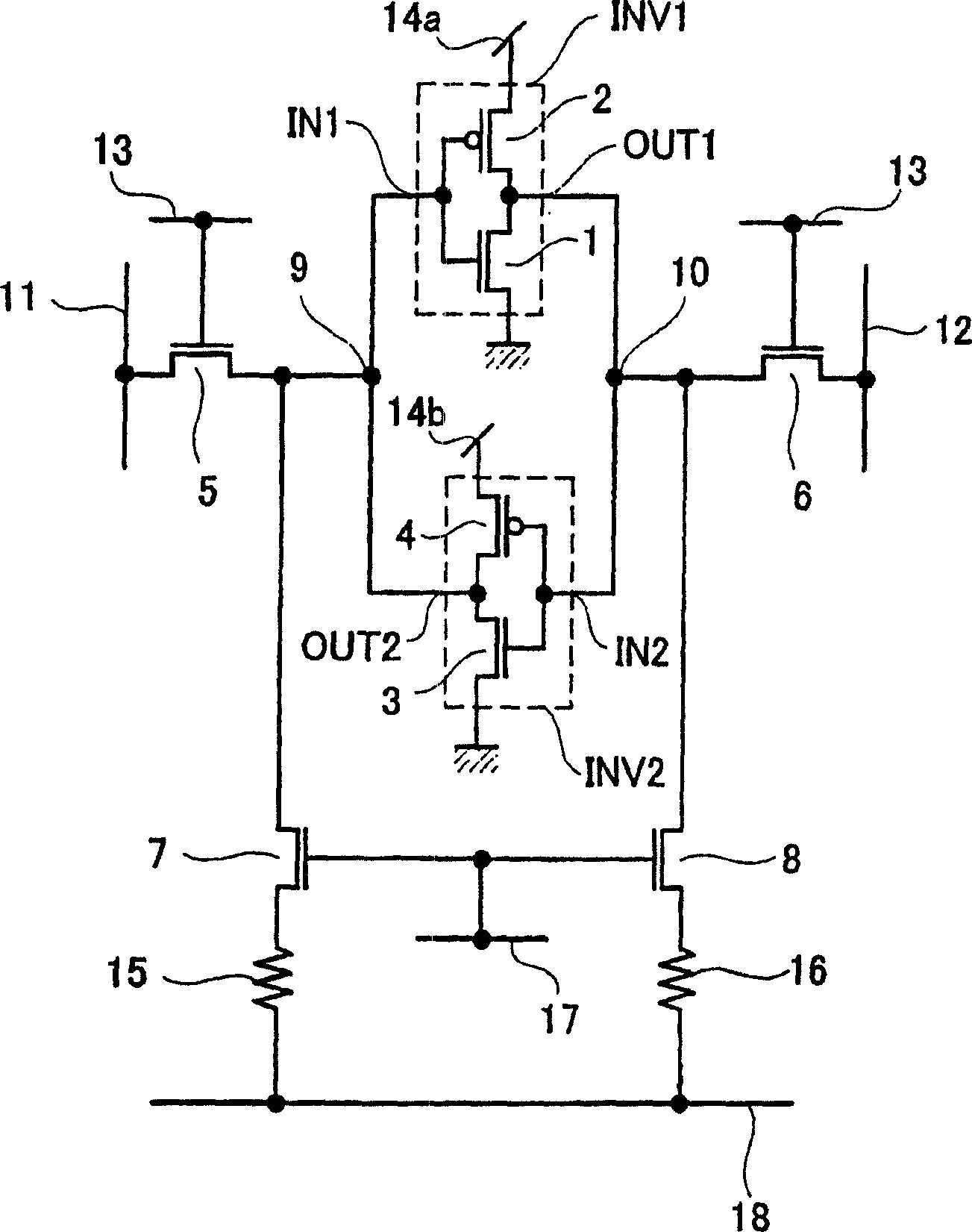
[0021] Embodiments of the present invention will be described below with reference to the drawings. FIG. 1 is a circuit diagram showing a nonvolatile flip-flop circuit according to an embodiment of the present invention. This nonvolatile flip-flop circuit has a first transistor 1 and a second transistor 2 constituting a first inverter INV1, a third transistor 3 and a fourth transistor 4 constituting a second inverter INV2, The fifth transistor 5 and the sixth transistor 6 of the first and second bypass transistors, the first storage node 9 and the second storage node 10, the word line 13, the first bit line 11 and the second bit line 12, the first and the second power supply lines 14a and 14b, the seventh transistor 7 and the eighth transistor 8 of the first and second control switching elements, the first variable resistance element 15 and the second variable resistance element 16, and the CS of the control signal line. Line 17 and Plate Line 18. The first and second transi...


PUM


Abstract

The present invention is in the nonvolatile bistable multivibrator circuit in which the first and second storage nodes of the bistable multivibrator circuit are connected to the first and second variable resistance elements through control transistors. After changing both of the first and second variable resistance elements to low resistance in the storage step, among the first and second variable resistance elements, the variable resistance element connected to the storage node for storing "0" is still kept at Low resistance, only change the varistor element connected to the storage node storing "1" to high resistance, and perform sequentially in the rechecking step to store "1" on the storage node connected to the varistor element with high resistance, in A driving method of a non-volatile bistable multivibrator circuit that stores "0" on a storage node connected to a low-resistance varistor element.

Description

technical field [0001] The present invention relates to a driving method of a nonvolatile bistable multivibrator circuit using a varistor element, and in particular to a nonvolatile bistable multivibrator circuit capable of nonvolatile operation during normal operation, high-speed operation, power off, etc. A driving method for a steady-state multivibrator circuit. Background technique [0002] Due to the popularization of portable devices in recent years, miniaturization and low power consumption of semiconductor elements are required. In addition, the necessity of using nonvolatile memory in portable instruments has also increased. At present, flash memory, ferroelectric memory (Fe RAM) and the like are put into practical use as nonvolatile memories. Also, in portable devices, nonvolatile memories are sometimes mixed with logic circuits for the sake of miniaturization. In addition, semiconductor elements for data processing centered on Si chips require not only miniatur...

Claims


Application Information

Patent Timeline
Patent Type & Authority Applications(China)
IPC IPC(8): G11C14/00H01L27/10H03K3/356
CPCG11C13/0004G11C14/0072G11C14/009H01L27/101H03K3/356008
Inventor 丰田健治大塚隆
Owner PANASONIC CORP
Why Eureka
Try Eureka