Dehumidifier case with water trough

A technology for dehumidifiers and sinks, used in heating and ventilation hoods/covers, etc., can solve problems such as condensate outflow, and achieve the effect of simple connection

Inactive Publication Date: 2005-12-28
LG ELECTRONICS (TIANJIN) APPLIANCES CO LTD
View PDF0 Cites 5 Cited by
  • Summary
  • Abstract
  • Description
  • Claims
  • Application Information

AI Technical Summary

Problems solved by technology

[0012] According to the tank (8) of the prior art, although the tank cover (8a) communicating with the drain hole (7a) is housed above the tank (8), the tank cover (8a) is simply placed on the tank (8), In the process of moving the user to pour out the condensed water, there is a problem that the condensed water flows out of the water tank (8) after pushing out the water tank cover (8a) when shaking violently

Method used


Image

  • Dehumidifier case with water trough
  • Dehumidifier case with water trough
  • Dehumidifier case with water trough

Examples


Embodiment Construction

[0037] The present invention will be described in detail below with reference to the accompanying drawings and embodiments.

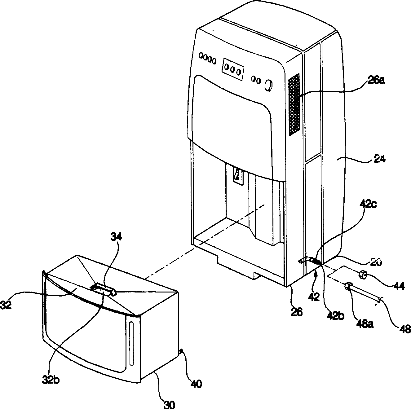
[0038] figure 1 It is a schematic diagram of the decomposition structure of the water tank separated from the dehumidifier in the present invention.

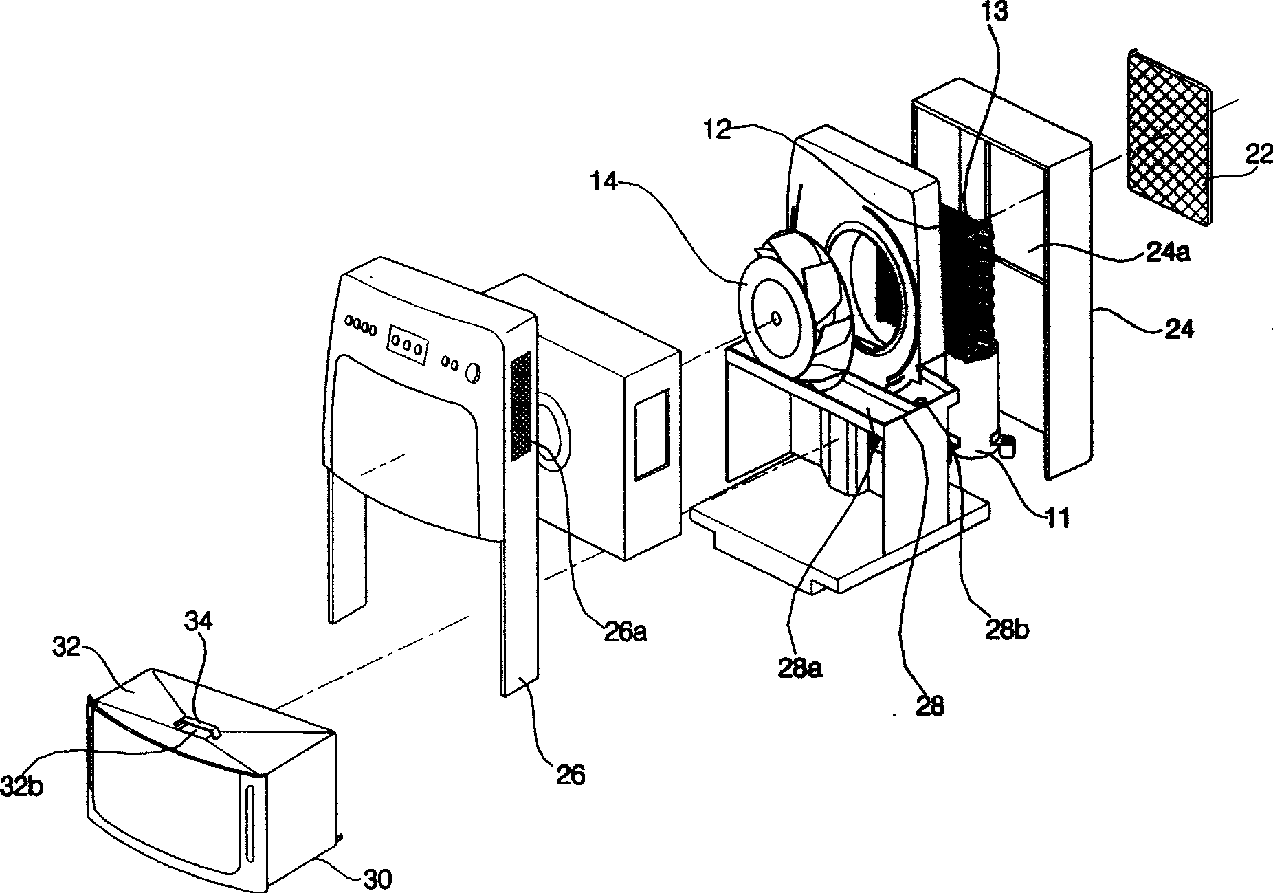
[0039] figure 2 yes figure 1 Schematic diagram of the breakdown structure.

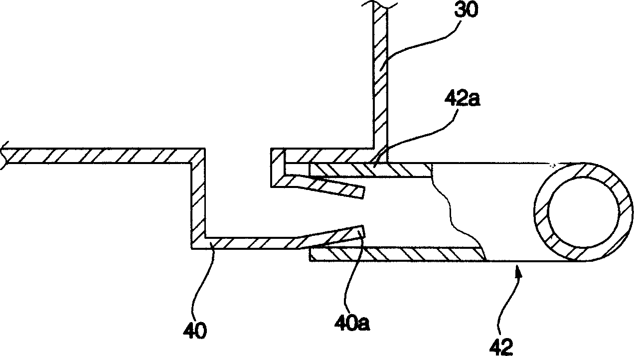
[0040] image 3 yes figure 2 Schematic diagram of the longitudinal section structure of the junction of the discharge pipe of the middle tank.

[0041] Such as Figure 1-Figure 3 As shown, the dehumidifier of the present invention includes a compressor (11) for compressing refrigerant, a condenser (12) for exchanging heat between the refrigerant compressed by the compressor (11) and air to condense the refrigerant, and passing through the condenser ( 12) The condensed refrigerant exchanges heat with the air in the evaporator (13) for evaporating heat, in order to improve the efficiency of the evaporator (13) and conden...


PUM


Abstract

A casing containing a water tank for demoistener features that a heat exchanger, a draining tray for collecting the condensed water of heat exchanger, and a water tank for storing the condensed water are contained in the casing. Said water tank features that when it is swinging the water can not flow out and the condensed water can flow in it only via a hole on the water tank.

Description

technical field [0001] The invention relates to an air conditioning device characterized by dehumidification treatment, in particular to a dehumidifier casing equipped with a water tank. Background technique [0002] Generally speaking, a dehumidifier sucks the humid air in the room into the case, uses a heat exchanger composed of a condenser and an evaporator refrigerated by flowing refrigerant to reduce the humidity, and then discharges the dehumidified air through the heat exchanger into the room. A device for reducing indoor humidity. [0003] Figure 4 It is a schematic diagram of the decomposition structure of the separation tank in the prior art dehumidifier, and Fig. 5 is a schematic diagram of the decomposition structure of the prior art dehumidifier. [0004] The dehumidifier of the prior art includes a compressor (1) for compressing refrigerant; a condenser (2) for heat-exchanging the refrigerant compressed by the compressor (1) with air to condense the refrigera...

Claims


Application Information

Patent Timeline
IPC IPC(8): F24F13/20
Inventor 郑哲新
Owner LG ELECTRONICS (TIANJIN) APPLIANCES CO LTD
Why Eureka
Try Eureka