Eureka AIR delivers breakthrough ideas for toughest innovation challenges, trusted by R&D personnel around the world.

Electrophoretic display panel

A display panel and electrophoretic display technology, applied in static indicators, nonlinear optics, instruments, etc., can solve problems such as poor image quality, non-negligible pixel appearance dependence, and short time intervals

Inactive Publication Date: 2005-12-28
KONINKLIJKE PHILIPS ELECTRONICS NV
View PDF3 Cites 3 Cited by
  • Summary
  • Abstract
  • Description
  • Claims
  • Application Information

AI Technical Summary

Problems solved by technology

However, since the time interval for controlling the preset potential difference and the image potential difference that is intended to be available is usually fixed and in the range between 100ms and 200ms, the preset potential difference and the image potential difference The available time intervals of ϕ are relatively short, and the appearance dependence of pixels in the history process is still not negligible
As a result, the displayed image still has relatively poor image quality
[0012] When controlling the preset potential difference and the time interval available for the image potential difference is fixed and in the range of 100 ms and 200 ms, it is a disadvantage of the described display panel that it is difficult to obtain a relatively high image quality with it

Method used


Image

  • Electrophoretic display panel
  • Electrophoretic display panel
  • Electrophoretic display panel

Examples


Embodiment Construction

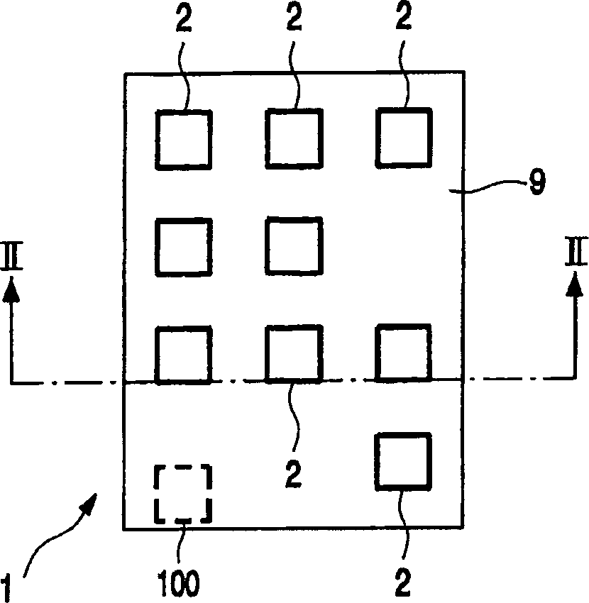
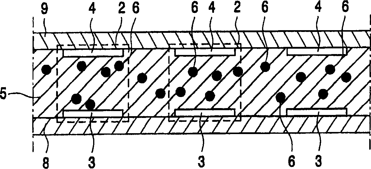
[0032] figure 1 and 2 An embodiment of a display panel 1 is shown having a first substrate 8 , an opposite second substrate 9 and a plurality of pixels 2 . Preferably, the pixels 2 are arranged in a two-dimensional structure substantially along a straight line. It is also possible for the pixels 2 to be in other arrangements, such as a honeycomb arrangement. An electrophoretic medium 5 with charged particles 6 is placed between the substrates 8 , 9 . First and second electrodes 3 , 4 are associated with each pixel 2 . The electrodes 3, 4 are capable of receiving a potential difference. exist figure 2, the first substrate 8 has a first electrode 3 for each pixel 2 , and the second substrate 9 has a second electrode 4 for each pixel 2 . The charged particles 6 can occupy end positions near the electrodes 3 , 4 and intermediate positions between the electrodes 3 , 4 . Each pixel 2 has an appearance determined by the position of the charged particles 6 between the electrod...


PUM


Abstract

The electrophoretic display panel ( 1 ), for displaying a picture, has drive means ( 100 ) which are arranged for controlling the potential difference of each picture element ( 2 ) to be a preset potential difference having a predetermined duration and subsequently to be a picture potential difference having an actual duration in the range between a smallest duration and a largest duration. For the display panel ( 1 ) to be able to provide a relatively high picture quality even when the interval available for controlling both the preset potential differences and the picture potential differences is constant and in the range between 100 ms and 200 ms, the drive means ( 100 ) are further arranged for controlling for each picture element ( 2 ) of at least a number of the picture elements ( 2 ) having smaller durations of the picture potential differences than the largest duration, the preset potential difference to have an additional duration, which is chosen in a range from larger than zero to equal to a difference between the largest duration and the actual duration of the picture potential difference.

Description

technical field [0001] The invention relates to an electrophoretic display panel for displaying images, comprising: [0002] - an electrophoretic medium comprising charged particles; [0003] - multiple pixels; [0004] - first and second electrodes associated with each pixel for receiving a potential difference; and [0005] - drive unit, [0006] Charged particles are able to occupy end positions near the electrodes and intermediate positions between the electrodes, [0007] The driver is configured to control the potential difference of each pixel [0008] - is a preset potential difference having a series of preset values ​​of alternating sign and having a predetermined duration, each preset value having a sub-duration denoting enough to present one of the end positions in said The energy released by the particles from their position, but not enough for the particles to reach the other end position, then [0009] - is the image potential difference, which has a value...

Claims


Application Information

Patent Timeline
IPC IPC(8): G02F1/167G09G3/20G09G3/34
CPCG02F1/167G09G3/2014G09G3/344G09G2310/0251G09G2310/06G09G2310/066G09G2310/068G09G2320/0247G09G2320/0252G02F1/1685
Inventor G·周M·T·约翰逊P·A·杜恩
Owner KONINKLIJKE PHILIPS ELECTRONICS NV
Why Eureka
Eureka Blog
Learn More