Device for tapwater pipe line directly pressurizating

A technology of tap water pipelines and booster devices, applied in water supply devices, water supply main pipelines, water supply pipeline systems, etc., can solve problems such as unavailability of pipeline pressure, water source end pipes affecting normal water use of water source end users, secondary pollution, etc.

Active Publication Date: 2006-01-11
姜全德 +2
View PDF0 Cites 3 Cited by
  • Summary
  • Abstract
  • Description
  • Claims
  • Application Information

AI Technical Summary

Problems solved by technology

[0002] The long-distance transportation of tap water will cause head loss. With the emergence of high-rise buildings, the pressure of municipal water supply will be insufficient. In order to ensure the normal water use of long-distance and high-rise residents, pressurization is required.
Boosting, if a booster pump is used directly on the pipeline, it will cause negative pressure in the pipeline at the water source end and affect the normal water use of the water source end users
For this reason, people generally used the partition water intake pressurization method in the past, specifically, a reservoir is set, the water in the water source end pipeline flows into the reservoir, and then the water in the reservoir is pumped into the next section of the pipeline, This is used to achieve pressurization, but the original pipeline pressure cannot be used in this way, resulting in a large loss of power consumption, waste of resources, and easy to cause secondary pollution
For this reason, people have developed a non-negative pressure pipeline direct pressurized water supply device. Its working principle is: directly take water from the pipeline to pressurize, and can use the original pressure of the pipeline. In order to avoid negative pressure in the pipeline, a steady flow compensator is set. , When the pipeline generates negative pressure, air is added, but when entering this working state, the original pipeline network pressure can no longer be used, all energy is released ineffectively, and the adjustable function of the flow rate is very weak

Method used


Image

  • Device for tapwater pipe line directly pressurizating

Examples


Embodiment

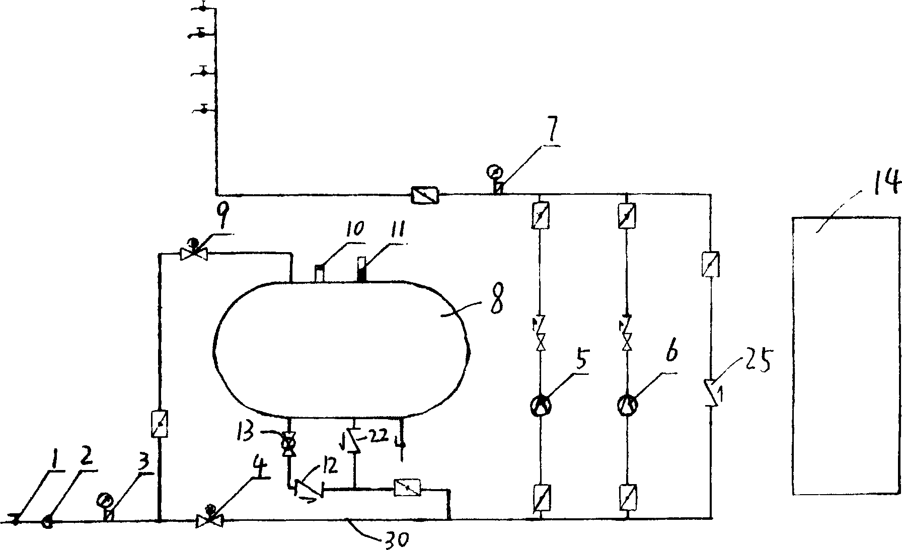
[0015] Example: see figure 1 , a direct pressurization device for tap water pipelines, mainly comprising: a first pressure gauge 3, a first electric valve 4, a first water pump 5, a second water pump 6, a second pressure gauge, a water collection tank 8, and a second electric valve 9 , the first check valve 12, the pipeline pump 13, the control cabinet 14, the water outlet of the first pressure gauge 3 communicates with the water inlets of the first and second electric valves 4 and 9 at the same time, and the water outlet of the second electric valve 9 communicates with the water outlet through the pipeline The water inlet of the water collecting tank 8 is connected, and the water collecting tank 8 is provided with three water outlets, the first water outlet is connected with the water inlet of the pipeline pump 13, and the second water outlet is connected with the water inlet of the second check valve 22, The third water outlet is provided with a gate valve for emptying. The ...


PUM


Abstract

The present invention discloses the running water pipeline direct pressurization equipment. Said equipment includes the components of electric valve, check valve, water pump and water-collecting tank. Said equipment is controlled by microcomputer. Said invention also provides the working principle of said equipment and its operation method.

Description

technical field [0001] The invention relates to a tap water booster. Background technique [0002] The long-distance transportation of tap water will cause head loss. With the emergence of high-rise buildings, the pressure of municipal water supply will be insufficient. In order to ensure the normal water use of long-distance and high-rise residents, pressurization is required. Boosting, if a booster pump is used directly on the pipeline, it will cause negative pressure in the pipeline at the water source end and affect the normal water use of the water source end users. For this reason, people generally used the partition water intake pressurization method in the past, specifically, a reservoir is set, the water in the water source end pipeline flows into the reservoir, and then the water in the reservoir is pumped into the next section of the pipeline, This is used to achieve pressurization, but the original pipeline pressure cannot be utilized in this way, resulting in a...

Claims


Application Information

Patent Timeline
Patent Type & Authority Applications(China)
IPC IPC(8): E03B7/00E03B7/07E03B7/09
CPCY02A20/00
Inventor 姜全德戴文元狄鹰
Owner 姜全德
Why Eureka
Try Eureka