New prefabricated landscape overflow weir

A prefabricated overflow weir technology, which is applied in barrage/weir, sea area engineering, construction, etc., can solve the problems of non-adjustable overflow weir, slow installation and disassembly, etc.

Active Publication Date: 2020-10-23
NANJING HYDRAULIC RES INST
View PDF4 Cites 0 Cited by
  • Summary
  • Abstract
  • Description
  • Claims
  • Application Information

AI Technical Summary

Problems solved by technology

[0004] The purpose of the present invention is to solve the problem of slow installation and disassembly, and the overflow weir is not adjustable, and proposes a new type of prefabricated landscape overflow weir

Method used


Image

  • New prefabricated landscape overflow weir
  • New prefabricated landscape overflow weir
  • New prefabricated landscape overflow weir

Examples


Embodiment 1

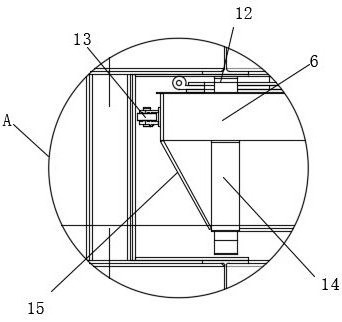
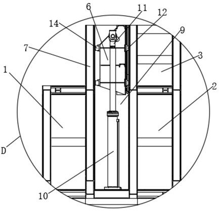
[0037] The new prefabricated landscape overflow weir includes a fixed frame 1, a stable frame 2, a bearing frame 3, a fixed steel pipe 4, a steel pipe groove 5, a straight lift gate 6 and a straight lift frame 7, the left side of the straight lift frame 7 and the right side of the fixed frame 1 The sides are fixedly connected, the right side of the lift frame 7 is fixedly connected with the left side of the stable frame 2, the upper end of the stable frame 2 is fixedly connected with the lower end of the bearing frame 3, steel pipe grooves are arranged on the left and right sides of the fixed frame 1, the stable frame 2 and the bearing frame 3 5. The fixed steel pipe 4 is movably socketed inside the steel pipe groove 5, and the vertical door 6 is movably socketed inside the lift frame 7. The outer side of the stable frame 2 and the bearing frame 3 are fixedly connected with the steel sheet pile 8 side, and the fixed The outer side of frame 1 is also fixedly connected with one s...

Embodiment 2

[0040] Embodiment 2: the difference based on Embodiment 1 is;

[0041] S1, survey the height of the river bottom, and determine the installation position of the fixed steel pipe 4;

[0042] S2, drive the fixed steel pipe 4 into the bottom of the river with a pile driver, and pay attention to controlling the relative size;

[0043] S3, fill up the river bottom in the area 4 of the 4 fixed steel pipes with gravel;

[0044] S4, align the steel pipe groove 5 on the weir body with 4 fixed steel pipes 4, and put it into the river bottom;

[0045] S5, the space between the fixed steel pipe 4 and the steel pipe groove 5 is poured with concrete;

[0046] S6. After the concrete is solidified, drive the steel sheet piles 8 on both sides into the river bottom;

[0047] S7. After fixing the steel sheet piles 8 on both sides, fill the gap with backfill soil and compact it;

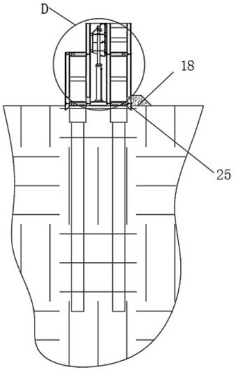
[0048] After the weir body of S4 is put into the river bottom, the underwater concrete 18 is filled on the side c...

Embodiment 3

[0050] Embodiment 3: the difference based on embodiment 1 and 2 is;

[0051] The steel sheet pile 8 is composed of a plurality of steel sheet pile assemblies 22, and the steel sheet pile assembly 22 includes a steel sheet pile beam 20, a steel sheet pile left connector 19 and a steel sheet pile right connector 21, and the left end of the steel sheet pile beam 20 is fixed to the right end of the steel sheet pile left connector 19 Connection, the right end of the steel sheet pile beam 20 is fixedly connected to the left end of the steel sheet pile right connector 21, the steel sheet pile left connector 19 matches the steel sheet pile right connector 21, and the steel sheet pile 8 adopts the SP-IV type Larsen steel sheet pile; the fixed frame 1 A plurality of support plates 16 and support slant columns 17 are provided on the outer side of the stability frame 2, the upper end of one support plate 16 is fixedly connected to one end of the support slant column 17, and the lower end o...


PUM


Abstract

The invention discloses a novel assembly type landscape overflow weir, and belongs to the field of overflow weirs. When the novel assembly type landscape overflow weir is used, it is ensured that theoverflow weir has the certain overflow capacity. When the novel assembly type landscape overflow weir is designed, the enough orifice size shape and high flow coefficient are achieved, so that the novel assembly type landscape overflow weir has the enough overflow capacity, the good orifice shape is achieved during designing, water can smoothly flow through the weir, harmful negative pressure, vibration, cavitation erosion and the like are not generated, it is ensured that local scouring damaging the safety of a weir body is avoided at an underwater bed, the position where the overflow weir section is located in the pivot should make the downstream water flowing state be smooth, reflection and scour flow is avoided, and normal operation of other buildings in the pivot is not affected and is in the working process.

Description

technical field [0001] The invention relates to the field of overflow weirs, in particular to a novel assembled landscape overflow weir. Background technique [0002] The overflow weir is a structure on which the liquid on the tray overflows. It has the function of maintaining the liquid layer on the tray and making the liquid overflow evenly. In order to fully mix the gas-liquid two-phase, the overflow weir should be used to maintain a certain clear liquid layer on the plate. As the clear liquid layer increases, the height of the two-phase mixture formed also increases, and the contact time and contact area also increase correspondingly. The more fully; but the pressure drop of the gas passing through the liquid layer also increases correspondingly, and the probability of liquid leakage will also increase. The height of the supernatant layer is equal to the sum of the height of the weir and the height of the supernatant layer of the weir, and the latter depends on the leng...

Claims


Application Information

Patent Timeline
Patent Type & Authority Patents(China)
IPC IPC(8): E02B7/26E02D27/40
CPCE02B7/26E02D27/40
Inventor 范子武陈正谢忱蔡秋鹏马振坤
Owner NANJING HYDRAULIC RES INST
Why Eureka
Try Eureka