Heat sink

A heat dissipation device and fan blade technology, which is applied to pump devices, components of pumping devices for elastic fluids, non-variable pumps, etc., can solve problems such as limited blower channel design

Active Publication Date: 2006-01-18
DELTA ELECTRONICS INC
View PDF0 Cites 10 Cited by
  • Summary
  • Abstract
  • Description
  • Claims
  • Application Information

AI Technical Summary

Problems solved by technology

However, in this traditional blower design, the blades 123 of the fan blade structure 12 are all arranged in the same outer...

Method used


Image

  • Heat sink
  • Heat sink
  • Heat sink

Examples


Embodiment Construction

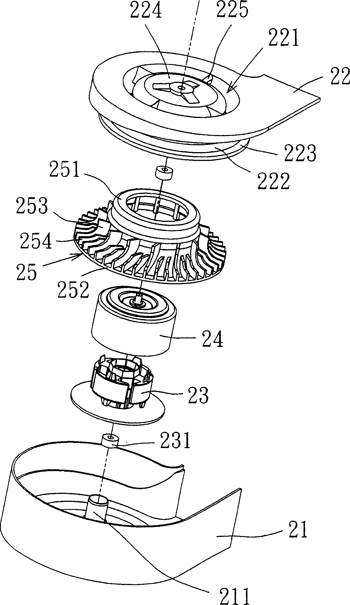
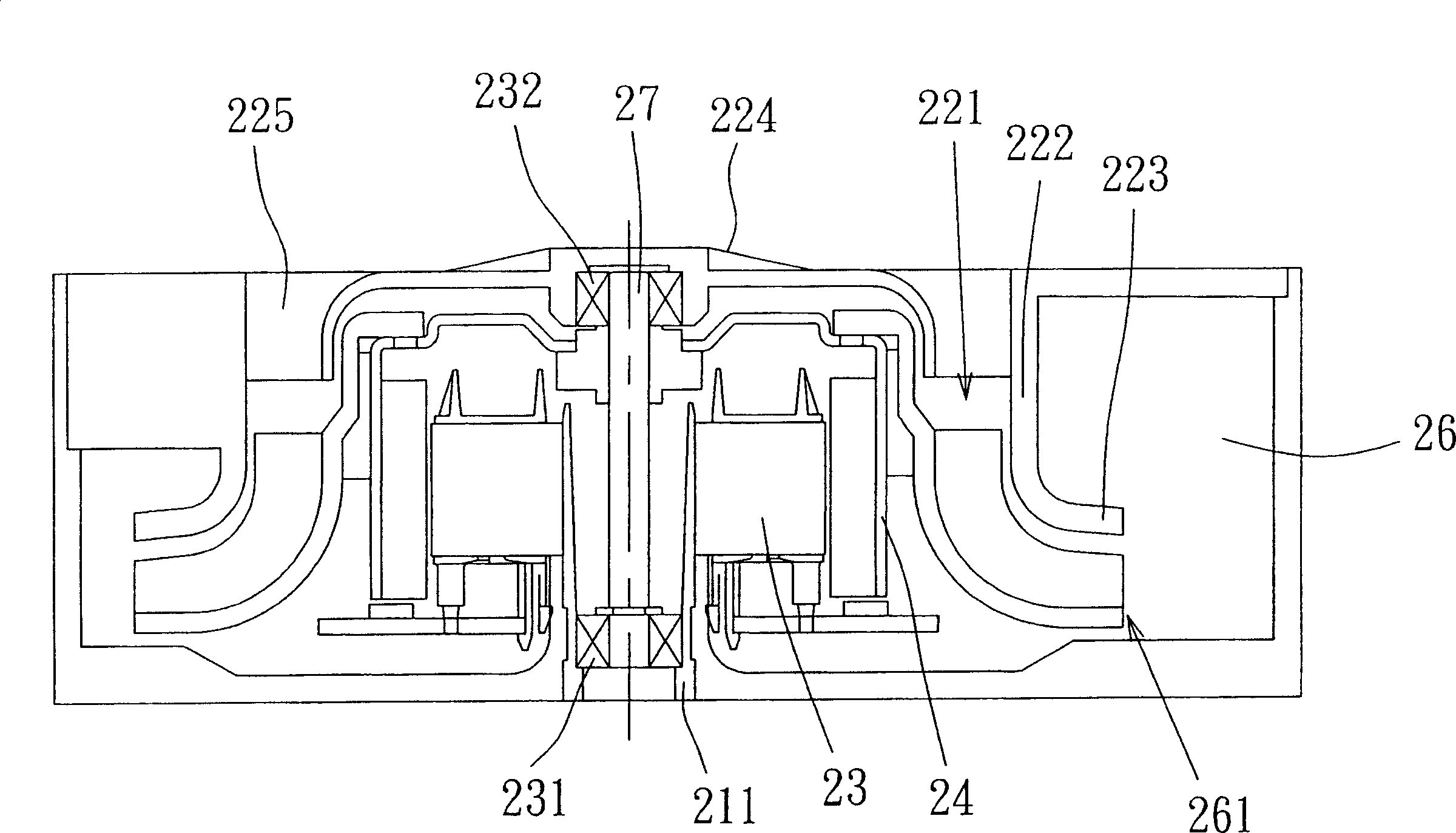
[0029] see Figure 2A to Figure 2C , which shows the first preferred embodiment of the heat sink of the present invention. In this embodiment, a centrifugal fan is taken as an example, but the design method can also be applied to an axial fan. The centrifugal fan is a one-way blower, which mainly includes a first frame 21 , a second frame 22 , a driving device 23 , an iron shell 24 and a rotor blade 25 . The first frame 21 has a socket seat 211 on which the driving device 23 can be placed, and a bearing 231 is placed in the socket seat 211 to support the rotating shaft 27 of the rotor blade portion 25 . The second frame 22 has an air inlet 221 and a wall 222 extending downward from the inner edge of the air inlet. When the second frame 22 is combined with the first frame 21, the second frame 22 The space formed after being combined with the first frame 21 is separated to define an air collecting channel 26 and a space for accommodating the moving blade portion 25 , and also ...


PUM


Abstract

This invention provides one compound fan dissipation device, which comprises the following parts: one fan frame with at least one entrance and exit; at least one dynamic fan located on the frame with one bottom, ring part, one first fan set and second fan, wherein, the first set is located outside the ring part and the second fan set is located on the bottom.

Description

technical field [0001] The invention relates to a heat dissipation device, in particular to a high-pressure centrifugal fan designed with composite fan blades. Background technique [0002] Generally existing blower, as shown in Figure 1, it comprises an outer frame 10, a motor 11, a blade structure 12 and a loam cake 13, wherein this outer frame 10 has an opening 101, as the air outlet of blower, The motor 11 is set on the base 102 of the outer frame 10 to rotate the blade structure 12 . The upper cover 13 has a circular opening 131 for the air inlet of the blower. The blade structure 12 further includes a hub 121 , an annular plate 122 and a plurality of blades 123 disposed on the upper and lower sides thereof. However, in the traditional blower design, the blades 123 of the fan blade structure 12 are all arranged in the same outer diameter and equal height, which will limit the design of the blower flow channel and the way of matching it. Contents of the invention ...

Claims


Application Information

Patent Timeline
IPC IPC(8): F04D29/44F04D29/30F04D25/08
Inventor 徐伟峻张楯成黄文喜张秀贞
Owner DELTA ELECTRONICS INC
Why Eureka
Try Eureka