Compact ultrathin water pump

A compact, water pump technology, applied in the direction of pumps, pump devices, pump components, etc., can solve the problem that the size and compactness of liquid cooling systems and ultra-thin water pumps cannot be met, the liquid cooling system is large, and the axial direction of the water pump cannot be satisfied. Increase in size and other issues to achieve the effect of improving fluid performance, wide application range, and reducing flow pressure loss

Pending Publication Date: 2021-07-13
东莞市鸿盈电子科技有限公司
View PDF0 Cites 1 Cited by
  • Summary
  • Abstract
  • Description
  • Claims
  • Application Information

AI Technical Summary

Problems solved by technology

However, in this conventional design, the circular water inlet is on the upper part of the water pump, so its axial size is limited by the size of the water inlet channel and cannot be further reduced.
[0003] like figure 1 and 2 As shown, it is a conventional centrifugal pump design. When a conventional centrifugal pump is used, a water tank needs to be added to the external water circuit to store cooling water. Due to the existence of the water tank, the entire liquid cooling system is relatively large.
At the same time, the connection between the water tank and the water pump is difficult to ensure watertightness; image 3 As shown, there is also an integrated water pump in the prior art, and its water tank is designed in series with the water pump body. Although it is convenient to use, this series connection leads to a further increase in the axial dimension of the water pump.
[0004] Therefore, the existing conventional water pumps are increasingly unable to meet the industry's requirements for the size and compactness of liquid cooling systems and ultra-thin water pumps

Method used


Image

  • Compact ultrathin water pump
  • Compact ultrathin water pump
  • Compact ultrathin water pump

Examples


Embodiment Construction

[0031] The technical solutions in this embodiment of the present invention will be clearly and completely described below in conjunction with the accompanying drawings in this embodiment of the present invention. Obviously, the described embodiment is an embodiment of the present invention, not all This embodiment. Based on this implementation manner in the present invention, all other implementation manners obtained by persons of ordinary skill in the art without making creative efforts fall within the protection scope of the present invention.

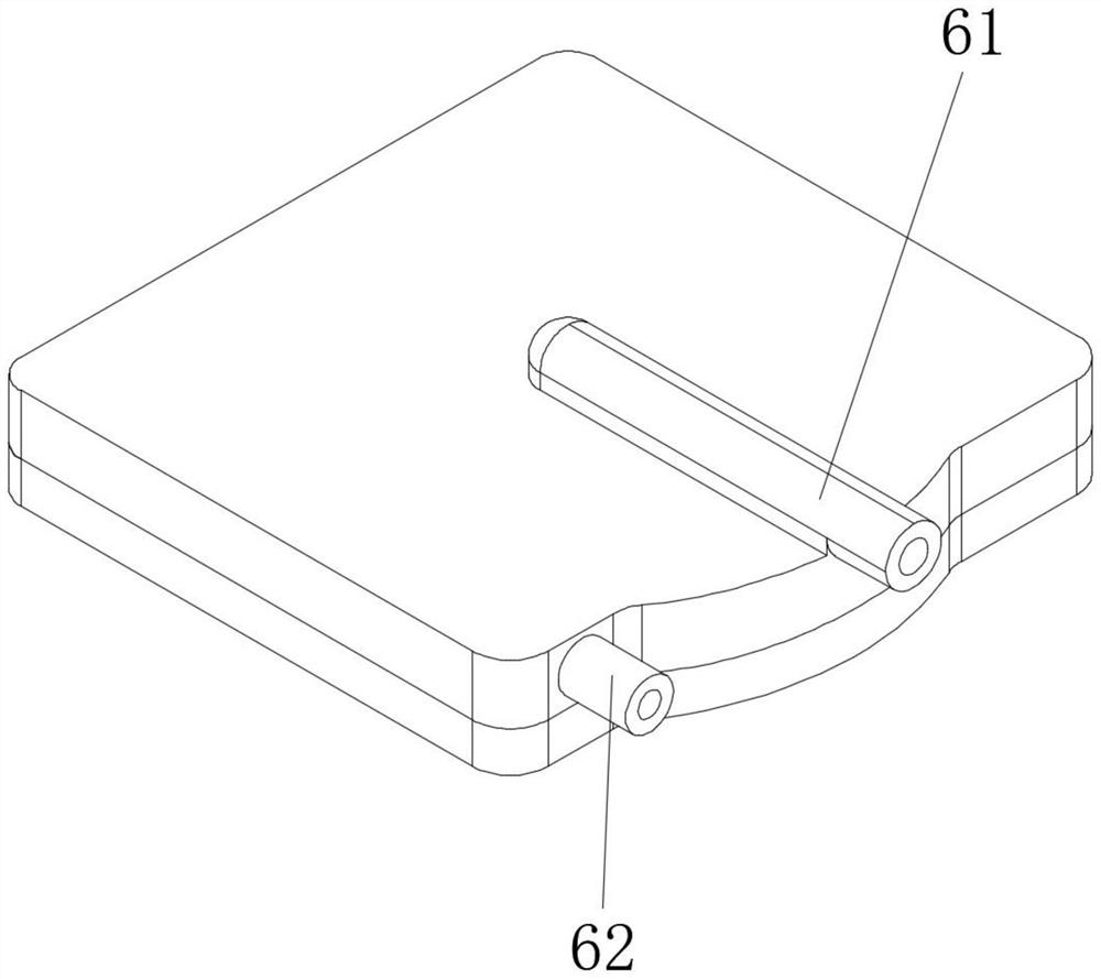
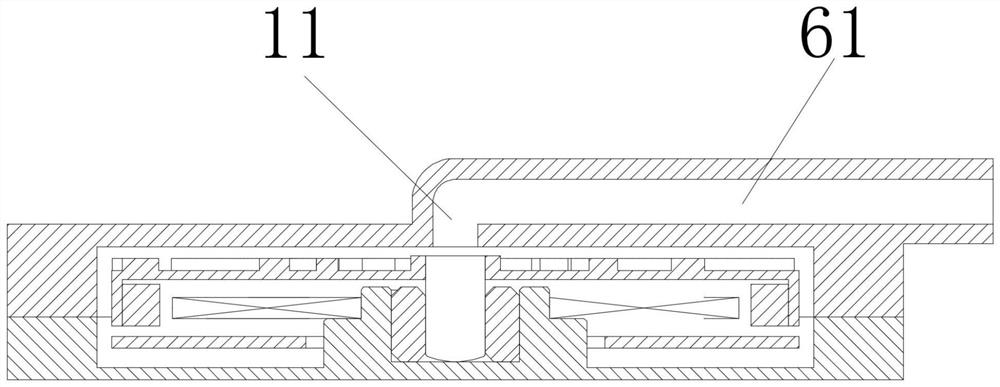
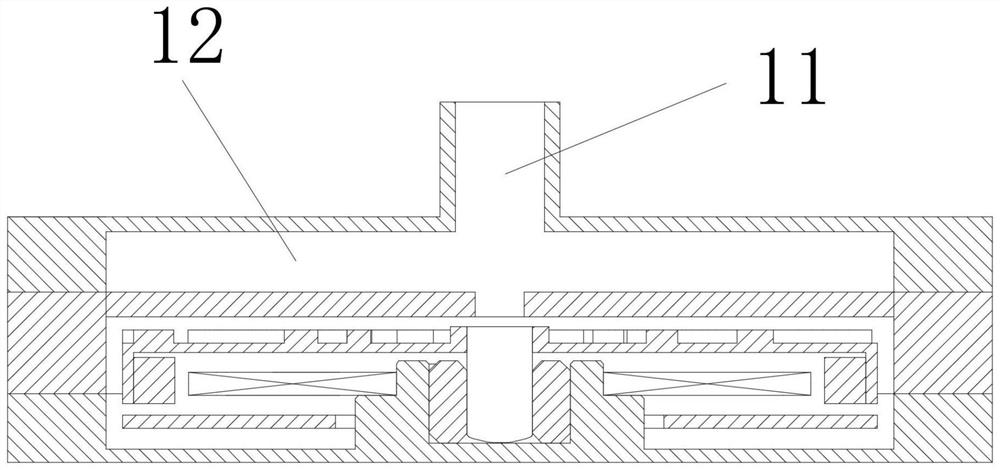
[0032] Please refer to Figure 4 to Figure 7 , the present invention provides a compact ultra-thin water pump, including a water pump body 10, the water pump body 10 includes a top cover 1, a pump casing 2 installed at the bottom of the top cover 1, and a base assembled at the bottom of the pump casing 2 3. The impeller assembly 4 is installed inside the pump casing 2, the stator assembly 5 is installed on the base assembly 3, the i...


PUM


Abstract

The invention discloses a compact ultrathin water pump which comprises a water pump body. The water pump body comprises a top cover, a pump shell and a base assembly. An impeller assembly is arranged in the pump shell, and a stator assembly is arranged on the base assembly. A water inlet connector is arranged on one side of the pump shell, and a water outlet connector is arranged on the other side of the pump shell. A first cavity is formed between the top cover and the pump shell, the first cavity comprises an annular water storage chamber separately arranged on the side face of the pump shell and an annular suction chamber arranged on the pump shell and communicated with the annular water storage chamber, and the water inlet connector is communicated with the annular water storage chamber. A second cavity is formed between the pump shell and the base assembly, an annular water pumping chamber is arranged on the outer side of the second cavity, the impeller assembly is arranged in the middle of the second cavity, the annular suction chamber is communicated with the annular water pumping chamber, and the annular water pumping chamber is communicated with the water outlet connector. The axial size of the water pump is obviously reduced, a water tank is integrated into the design of the water pump, and the compactness of the water pump is improved.

Description

technical field [0001] The invention relates to the technical field of water pumps, in particular to a compact ultra-thin water pump. Background technique [0002] There are more and more demands for ultra-thin water pumps in the industry. In order to reduce the axial length, conventional centrifugal pumps generally adopt the following flow channel design. Generally, the cooling water first flows into the circular water inlet horizontally, and then turns 90 degrees to axially flow into the impeller. , and finally flow out from the side of the impeller. However, in this conventional design, the circular water inlet is on the upper part of the water pump, so that its axial size cannot be further reduced due to the size of the water inlet flow channel. [0003] like figure 1 and 2 As shown, it is a conventional centrifugal pump design. When conventional centrifugal pumps are used, a water tank needs to be added to the external water circuit to store cooling water. Due to the...

Claims


Application Information

Patent Timeline
Patent Type & Authority Applications(China)
IPC IPC(8): F04D13/06F04D29/42
CPCF04D13/0666F04D29/426F04D29/4273
Inventor 贾自周
Owner 东莞市鸿盈电子科技有限公司
Why Eureka
Try Eureka