Process for stripping and a fluid catalytic cracking apparatus relating thereto

a fluid catalytic cracking and stripping technology, applied in the field of stripping in, can solve problems such as flow patterns, and achieve the effect of improving the performance of the fluid catalytic cracking apparatus

Inactive Publication Date: 2014-07-31
UOP LLC
View PDF5 Cites 1 Cited by
  • Summary
  • Abstract
  • Description
  • Claims
  • Application Information

AI Technical Summary

Benefits of technology

[0008]In the embodiments disclosed herein, providing macro-distribution of fluid flow lessens gas velocity downward and improves the performance of a fluid catalytic cracking apparatus. Particularly, the stripping vessel can have baffles spaced apart that allow the macro-distribution of fluid flow.

Problems solved by technology

Generally, many catalyst strippers include a support grid and steam distribution system that restricts the catalyst flow causing a conflict in flow patterns between the upward flowing steam and downward flowing catalyst.
Such flow restricted areas can tend to accumulate gas that may coalesce into large bubbles further restricting the flow of gas and catalyst.

Method used


Image

  • Process for stripping and a fluid catalytic cracking apparatus relating thereto
  • Process for stripping and a fluid catalytic cracking apparatus relating thereto
  • Process for stripping and a fluid catalytic cracking apparatus relating thereto

Examples


Embodiment Construction

[0016]An FCC apparatus may be used in an FCC process. Such an exemplary FCC apparatus and process are disclosed in, e.g., U.S. Ser. No. 13 / 492,025. The FCC apparatus can include a regenerator and a riser-reactor. The riser-reactor may include a reaction separation vessel, a stripping zone, and a riser. Generally, the feed can have a boiling point range of about 180-about 800° C. The feed can be at least one of a gas oil, a vacuum gas oil, an atmospheric gas oil, an atmospheric residue, and a vacuum residue. Alternatively, the feed may be at least one of a heavy cycle oil and a slurry oil. The feed may have a temperature of about 140-about 430° C., preferably about 200-about 290° C.

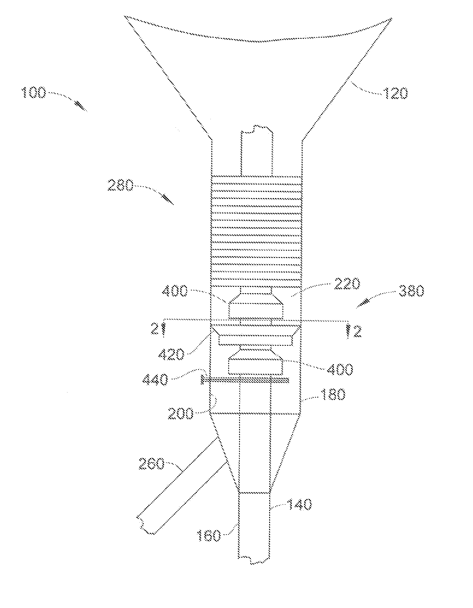
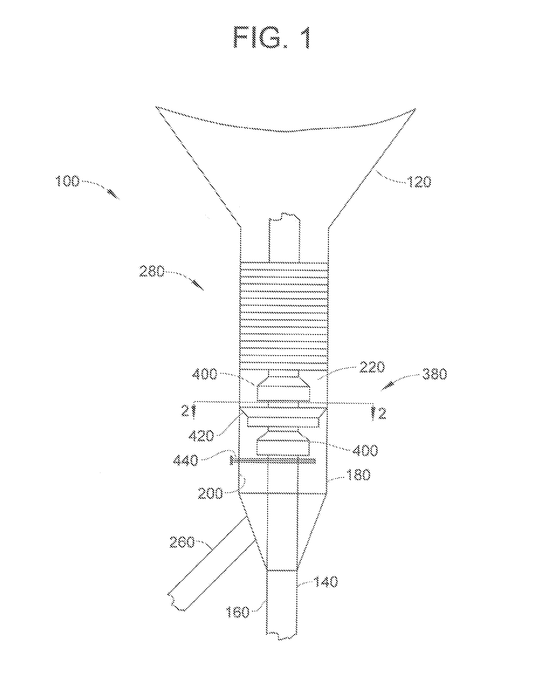
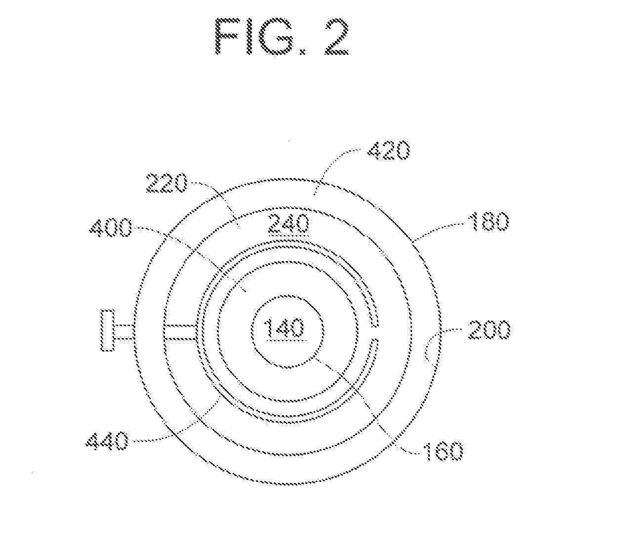
[0017]Referring to FIGS. 1-2, only a portion of the riser-reactor of an apparatus 100 is depicted, namely a riser 140, partially depicted, for providing the feed and catalyst to a reaction separation vessel 120, partially depicted, and a stripping vessel 180 at least partially or completely surrounding the...


PUM

PropertyMeasurementUnit
boiling pointaaaaaaaaaa
temperatureaaaaaaaaaa

Abstract

One exemplary embodiment can be a process for stripping. The process can include passing catalyst to a stripping vessel containing a riser, providing a plurality of baffles having a first baffle and a second baffle, and providing one or more packing layers. The stripping vessel and riser may define an annular zone including annular area for stripping of the catalyst, and the first and second baffles collectively overlap in no more than about 50% of the annular area. Often, the first baffle is coupled to an outer circumference of the riser and extends outward, and the second baffle is coupled to an inner circumference of the stripping vessel and extends inward. Typically, the one or more packing layers are within the annular zone.

Description

FIELD OF THE INVENTION[0001]This invention generally relates to a process for stripping in, e.g., a fluid catalytic cracking apparatus.DESCRIPTION OF THE RELATED ART[0002]Fluid catalytic cracking (which may be abbreviated as “FCC” herein) can be a catalytic conversion process for cracking heavy hydrocarbons into lighter hydrocarbons by bringing the heavy hydrocarbons into contact with a catalyst composed of finely divided particulate material in a fluidized reaction zone. Most FCC units use a zeolite-containing catalyst having high activity and selectivity. As the cracking reaction proceeds, substantial amounts of highly carbonaceous material, referred to as coke, may be deposited on the catalyst forming spent catalyst. Generally, a high temperature regeneration burns the coke from the spent catalyst. The regenerated catalyst may be cooled before being returned to the reaction zone. Typically, spent catalyst is continually removed from the reaction zone and replaced by essentially c...

Claims


Application Information

Patent Timeline
Patent Type & Authority Applications(United States)
IPC IPC(8): B01J8/00B01J38/00
CPCB01J38/00B01J8/0085B01J19/087B01J19/10B01J2219/182B01J38/06B01J38/12B01J38/30B01J29/90C10G11/18C10G11/182
Inventor HEDRICK, BRIAN W.PALMAS, PAOLO
Owner UOP LLC
Why Eureka
Try Eureka